Transcription of NI 9482 User Manual and Specifications - National Instruments
1 USER Manual AND SPECIFICATIONSNI 94824-Channel SPST Electromechanical Relay ais2| | ni 9482 This document describes how to use the National Instruments 9482 and includes Specifications and pin assignments for the ni 9482 . NoteThe safety guidelines and Specifications in this document are specific to the ni 9482 . The other components in the system might not meet the same safety ratings and Specifications . Refer to the documentation for each component in the system to determine the safety ratings and Specifications for the entire CompactDAQ & NI CompactRIO softwareversionChassis compatibilitySoftware SupportNI 9482| National Instruments |3 Safety GuidelinesOperate the ni 9482 only as described in these operating SurfaceThis icon denotes that the component may be hot.
2 Touching this component may result in bodily This icon denotes a warning advising you to take precautions to avoid electrical not operate the ni 9482 in a manner not specified in this user Manual . Product misuse can result in a hazard. You can compromise the safety protection built into the product if the product is damaged in any way. If the product is damaged, return it to National Instruments for Guidelines for Hazardous VoltagesIf hazardous voltages are connected to the module, take the following precautions.
3 A hazardous voltage is a voltage greater than Vpk or 60 VDC to earth | | ni 9482 CautionEnsure that hazardous voltage wiring is performed only by qualified personnel adhering to local electrical not mix hazardous voltage circuits and human-accessible circuits on the same sure that devices and circuits connected to the module are properly insulated from human module terminals are hazardous voltage LIVE (> VDC), you must ensure that devices and circuits connected to the module are properly insulated from human contact.
4 You must use the NI 9927 connector backshell kit to ensure that the terminals are not 9482| National Instruments |5 Figure 1. NI 9927 Electromagnetic Compatibility GuidelinesThis product was tested and complies with the regulatory requirements and limits for electromagnetic compatibility (EMC) as stated in the product Specifications . These requirements and limits are designed to provide reasonable protection against harmful interference when the product is operated in its intended operational electromagnetic | | ni 9482 This product is intended for use in industrial locations.
5 There is no guarantee that harmful interference will not occur in a particular installation, when the product is connected to a test object, or if the product is used in residential areas. To minimize the potential for the product to cause interference to radio and television reception or to experience unacceptable performance degradation, install and use this product in strict accordance with the instructions in the product , any changes or modifications to the product not expressly approved by National Instruments could void your authority to operate it under your local regulatory ensure the specified EMC performance.
6 Operate this product only with shielded cables and I/O port pins of this product can be damaged if subjected to Electrostatic Discharge (ESD). To prevent damage, industry-standard ESD prevention measures must be employed during installation, maintenance, and 9482| National Instruments |7 CautionThe I/O port of this product is rated for Measurement Category II; however, it is neither designed nor tested for compliance with the transient immunity requirements for Electrical Fast Transients or lightning Surge, which are normally applied to ports intended for connection to the electrical distribution system.
7 For applications where connection to the electrical distribution system is desired, ensure that the I/O port is provided with appropriate transient | | ni 9482 Connecting the ni 9482 The ni 9482 provides connections for four electromechanical relay 2. ni 9482 Pinout030123456789CH0aCH0bCH1aCH1bCH2aCH 2bCH3aCH3bNCNCNI 9482| National Instruments |9 ConnectorThe ni 9482 has a 10-terminal, detachable screw-terminal channel has two interchangeable pins, CHa and CHb, to which you can connect a must use 2-wire ferrules to create a secure connection when connecting more than one wire to a single terminal on the NI channel has an LED that indicates the state of the channel.
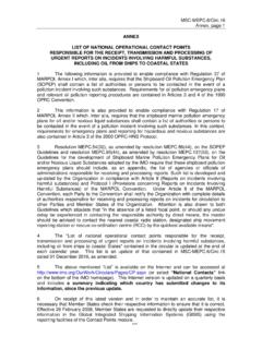
8 A channel LED is lit when the channel is on and dark when the channel is off. The LEDs are disabled when the chassis is in sleep InformationSleep Mode on page 1210| | ni 9482 Connecting a LoadYou can connect loads to the ni 9482 . Connect the positive lead of the load to CHa or CHb, the ground of the load to the power supply, and the remaining CHa or CHb to the other lead of the power 3. Connecting a LoadWhen the channel is turned on, the terminal connected to the load drives current or applies voltage to the load.
9 When the channel is off, the terminal does not drive current or apply voltage to the 9482+ CHaCHbACorLoadNI 9482| National Instruments |11 Wiring for High-Vibration ApplicationsIf an application using the ni 9482 is subject to high vibration, National Instruments recommends that you either use ferrules to terminate wires to the detachable screw-terminal connector or use the NI 9927 backshell kit to protect the 4. Wiring a Screw-Terminal Connector with a Ferrule12| | ni 9482 Sleep ModeThis module supports a low-power sleep mode.
10 Support for sleep mode at the system level depends on the chassis that the module is plugged into. Refer to the chassis Manual for information about support for sleep mode. If the chassis supports sleep mode, refer to the software help for information about enabling sleep , when a system is in sleep mode, you cannot communicate with the modules. In sleep mode, the system consumes minimal power and may dissipate less heat than it does in normal InformationPower Requirements on page 14 SpecificationsThe following Specifications are typical for the range -40 C to 70 C unless otherwise the ni 9482 in a manner not described in this document may impair the protection the ni 9482 9482| National Instruments |13 Output CharacteristicsNumber of channels.