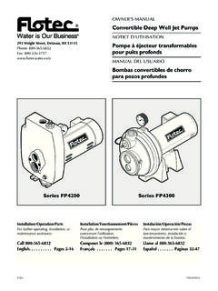
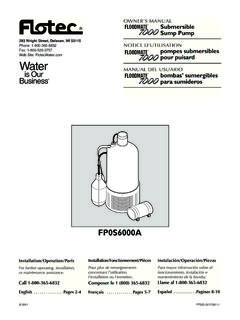
Transcription of NOTICE D’UTILISATION Pompe submersible de 4 po
1 Installation/Operation/PartsFor further operating, installation, or maintenance assistance: Call 1-800-365-6832 English .. Pages 2-12 Installation/Fonctionnement/Pi cesPour plus de renseignements concernant l utilisation,l installation ou l entretien,Composer le 1 (800) 365-6832 Fran ais .. Pages 13-24 Instalaci n/Operaci n/PiezasPara mayor informaci n sobre el funcionamiento, instalaci n o mantenimiento de la bomba:Llame al 1-800-365-6832 Espa ol ..Paginas 25-36 2012 FP874 (07/26/12) 3315 0898 OWNER S MANUAL4 submersible PumpsTwo and Three Wire, 1/2 thru 11 2 HP, 60 HzNOTICE D UTILISATIONP ompe submersible de 4 po deux et trois fils, de 1/2 11 2 ch, 60 HzMANUAL DEL USUARIOB ombas sumergibles de 4 de dos y tres hilos, 1/2 a 11 2 CV, 60 Hz293 Wright Street, Delavan, WI 53115 Phone: 800-365-6832 Fax.
2 Safety InstructionsSAVE THESE INSTRUCTIONS - This manual contains important instructions that should be followed during installation, operation, and maintenance of the product. This is the safety alert symbol. When you see this symbol on your pump or in this manual, look for one of the following signal words and be alert to the potential for personal injury! indicates a hazard which, if not avoided, will result in death or serious injury. indicates a hazard which, if not avoided, could result in death or serious injury. indicates a hazard which, if not avoided, could result in minor or moderate addresses practices not related to personal read and follow all safety instructions in this manual and on safety labels in good condition.
3 Replace missing or damaged safety Proposition 65 Warning This product and related accessories contain chemicals known to the State of California to cause cancer, birth defects or other reproductive Risk of hazardous pressure. Under certain conditions, submersible pumps can develop extremely high pressure. Install a pressure relief valve capable of passing entire pump flow at 75 PSI (517 kPa) when using an air over water pressure tank. Install a pressure relief valve capable of passing entire pump flow at 100 PSI (690 kPa) when using a pre-charged pressure tank.
4 Risk of flooding. Can cause personal injury and/or property damage. Do not allow pump, pressure tank, piping, or any other system component containing water to freeze. Freezing may damage system, leading to injury or flooding. Allowing pump or system components to freeze will void Risk of electric shock. Can shock, burn or kill. To avoid dangerous or fatal electric shock hazard, use pump only in a water well. Risk of electric shock. Can shock, burn or kill. Do not install this pump in any pond, river, or other open body of water that could be used for swimming or recreation.
5 Do not swim, wade or play in a body of water in which a submersible pump has been installed. Install, ground and wire pump according to local code and National Electrical Code requirements. Disconnect electrical power supply before installing or servicing pump. Make sure line voltage and frequency of power supply match motor nameplate voltage and Install pump according to all plumbing, pump and well code Test well water for purity before using well. Call your local health department for testing During installation, keep well covered as much as possible to prevent leaves and foreign matter from falling into well.
6 Foreign objects in well can contaminate the water and cause serious mechanical damage to the Pipe joint compound can cause cracking in plastics. Use only teflon tape when sealing joints in plastic pipe or connecting pipe to thermoplastic of contents Safety Instructions ..2 Pre-Installation ..2 Electrical ..2-6 Installation ..6 Initial Startup ..6-7 Connecting to Tank/Water System ..7-9 Troubleshooting Guide ..10-11 Warranty ..12 Pre-installationInspect pump and motor for delivery damage. Report any damage immediately to the shipping carrier or to your well driller should thoroughly develop the well (that is, pump out all fine sand and foreign matter) before pump is installed.
7 See Initial Start-Up, Page performance is based on pumping clear, cold, liquid water with no entrained is void in the following conditions: If pump has pumped excessive sand excessive sand can cause premature wear to pump. If water is corrosive. If entrained gas or air are present in the water being pumped these can reduce flow and cause cavitation which can damage pump. If pump has been operated with discharge valve closed severe internal damage will pump at least 15 to 20 ( to 6 M) below the lowest water level reached with pump running (lowest draw-down water level), and at least 5 ( ) above the bottom of the Risk of electric shock.
8 Can shock, burn or kill. Permanently ground pump, motor and control box before connecting power supply to Motors: 1 Ph, 2-Wire Cable, 60 Hz. Wire Size Wire Size, AWG HP Volt 14 12 10 8 6 4 3 2 1 0 00 115 110 174 278 440 685 1092 1373 1734 2184 2757 3479 230 438 697 1112 1761 2740 4369 5492 6936 8738 11029 230 365 581 927 1468 2284 3641 4577 5780 7281 9191 11596 1 230
9 304 484 772 1223 1903 3034 3814 4817 6068 7659 96632-Wire Ground pump and motor in accordance with the local codes and ordinances. Use a copper ground wire at least as large as wires carrying current to is supplied with a copper ground this ground wire to a copper conductor that matches motor wire size specified in Table 1II. See Page 5 for wire splicing ground pump, motor and control box before connecting power cable to power supply. Connect ground wire to approved ground first and then connect to equipment being not ground to a gas supply line.
10 Rish of electrical shock and fire. Can shock, burn or kill. If using a drop wire larger than No. 10 ( ) (for example, No. 8 ( ) wire) between pump and control box, run wire to a separate junction box. Connect junction box to control box with a No. 10 ( ) or smaller wire (depending on amp rating of pump see Table 1II). For more information, contact your local code ConnectionsAll wiring must meet National Electrical Code or Canadian Electrical Code and local code require only copper wire when making connections to pump and control avoid over-heating wire and excessive voltage drop at motor, be sure that wire size is at least as large as size listed in Table 1II for your horsepower pump and length of wire When built-in overheating protection is not provided.


![AGITADORES SUMERGIBLES.ppt [Modo de compatibilidad]](/cache/preview/f/9/8/2/e/f/1/3/thumb-f982ef135e662dcfcf15b4188a5390f7.jpg)