Transcription of Notification Appliance Circuit Module - Bosch …
1 Notification Appliance Circuit ModuleD192G enInstallation guide NoticesThese instructions cover the installation of the D192G Notification Appliance Circuit Module ina fire system supervised by a fire alarm control panel (FACP) or a combination Burglary/Firecontrol , test and maintain the Module according to these instructions, NFPA 72, local codes,and the authority having jurisdiction (AHJ). Failure to follow these instructions can result infailure of a detector to initiate an alarm event. Bosch Security Systems, Inc.
2 Is not responsiblefor improperly installed, tested or maintained installing the Module , become familiar with the Installation and Operation Guide for thecontrol panel you are Module uses only polarized (DC) signaling devices. Not all signaling devices are signaling devices used with the Module must: be polarized (DC) signaling devices. match the voltage rating of the alarm power supply. not exceed the current rating of the alarm power supply. not exceed 3 A per Module . total no more than 12 D192G modules per system.
3 !Warning!Follow these instructions to avoid personal injury and damage to 72 requires that you perform a complete system wide functional test following anymodifications, repair, upgrades or adjustments made to the system s components, hardware,wiring, programming and software/firmware. 1 Notification Appliance Circuit ModuleNotices | en3 Bosch Security Sustems, | 03 | Module is used for wiring connections to remote signaling devices. Wiring is supervisedfor open, short, or grounded Circuit can connect up to 12 D192G modules to the same system on the control panels listed inthe table below.
4 For the individual annunciation of an indicating bell Circuit , connect themodules to separate Module powers Notification appliances from the control panel power supply or from anUnderwriters Laboratories, Inc. (UL 1481) Listed auxiliary 12 VDC or 24 VDC regulated/power limited power supply for fire protective signaling units and commercial/residentialburglar units. This feature allows the system to support more signaling devices on longer wireruns. It also allows the use of 12 V or 24 V Notification appliances requiring the appropriatepower panelsCompatible modulesCompatible relaysSee section:Active Products:G-series (V2 andhigher)1 panelsD8128DD130, D133, D134 Wiring the modulewith G Series controlpanels, page 8B series panels2 D133, D134 Wiring the modulewith B Series controlpanels, page 12 Legacy Products*.
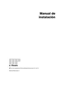
5 G3 panels*See control panel documentation on Bosch website ( )D9124*1 G-series (V2 and higher) = GV4 (D9412GV4, D7412GV4, and D7212GV4**), GV3(D9412GV3, D7412GV3, and D7212G3**), and GV2 (D9412GV2, D7412GV2, andD7212GV2**)2 B series = B5512**, B4512** and B3512**3 G = D9412G, D7412G, D7212G** Legacy products were investigated to comply only to UL864 8th edition** indicates products which are not UL Listed for commercial fire | NoticesNotification Appliance Circuit | 03 | guideBosch Security Sustems, : D192G_NAC_Module1 Power from the control panel s AUXPOWER6 Negative (-) connection from UL1481remote auxiliary power supply2 Connection to control panel sCOMMON Circuit ground (see Warningbelow)7 Positive (+) connection to the signalingdevice loop3 Connection to control panel zoneoutput8 Negative (-) connection to thesignaling device loop4 Connection to control panel sprogrammable alarm outputs9 Toggle switch for silencing theindicating devices5 Positive(+)
6 Connection to UL 1481remote auxiliary power supply10 Mounting holes !Warning!The D192G common (COM) terminals are digital ground, not earth ground. A ground faultcondition exists when the COM terminals are connected to earth ground. Notification Appliance Circuit ModuleNotices | en5 Bosch Security Sustems, | 03 | normal operation, the NAC loop is supervised for opens, shorts, and ground faults. Ifany of these conditions is detected, the control panel indicates a trouble condition at thecommand center. Program the control panel to report the condition to the central station.
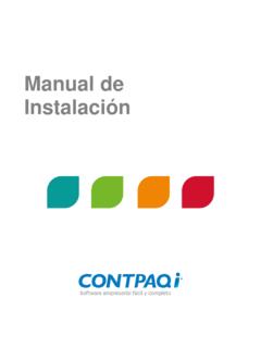
7 (See Programming, page 17.)When the control panel detects an alarm, the alarm output Circuit triggers the Module tosupply Circuit power to the NAC testing the alarm panel, the Module uses a toggle switch to silence the fire alarmindicating devices. When the toggle switch is in Silence Mode (off), the Module indicates asupervisory trouble condition to the control panel and the yellow SUPERVISION TROUBLE following table indicates possible causes for the various LED indicator patterns:IndicatorPossible causeSUPERVISION TROUBLE LED (yellow) is on.
8 Output loop or 560 EOL resistor isopen or missing. Alarm switch is in SILENCE (OFF) TROUBLE LED and ALARM LED(red) are off. Normal operation with no alarm ortrouble. No power. Check for voltage across theExternal Power In and Commonterminals. If the external voltage is notconnected, the control panel reports atrouble condition locally and to thecentral station (if connected). The wire to the Common terminal isopen or missing. If Common is notconnected, the control panel reports twotrouble conditions locally and to thecentral station (if connected).
9 ALARM LED is is an alarm. The LED follows theoperation of the output relay when the Alarmswitch is in the ON (NORMAL) TROUBLE and ALARM LEDs the Alarm switch is in the SILENCE (OFF)position and the Module is in alarm, both theSUPERVISION TROUBLE and ALARM : LED operation and troubleshooting 36en | NoticesNotification Appliance Circuit | 03 | guideBosch Security Sustems, connect without an external power supply: Mount the Module (s) inside the control panel enclosure using the supplied mountingscrews.
10 You can use any mounting position. For additional locations, use the D137 Mounting Bracket. Refer to the D137 Installation Instructions. If utilizing the Module in a commercial burglary application, use a UL Listed tamperswitch (such as the ICP-EZTS Cover Tamper Switch) on the enclosure. If installing the Module in a separate UL Listed enclosure such as a D8103, D8108A, orD8109 with a D9002 Mounting Plate, install the enclosure according to themanufacturer s instructions. For information on the mounting plate, refer to the D9002 Installation Instructions.