Transcription of nRF52840 Product Specification
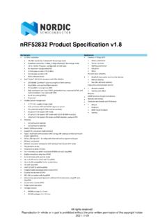
1 nRF52840 Objective Product Specification Key features Applications Bluetooth 5 ready multiprotocol radio Advanced wearables Bluetooth 5 data rate support: 2 Mbs, 1 Mbs, 500 kbs, 125 kbs Connected watches 32-bit ARM Cortex -M4F @ 64 MHz Advanced personal fitness devices High speed 2 Mbs data rate Wearables with wireless payment 104 dB link budget for Bluetooth low energy Connected health Full-speed 12 Mbs USB controller Virtual/Augmented Reality applications NFC-A tag on-chip Internet of Things (IoT). Software stacks available as downloads Smart home sensors and controllers Application development independent of protocol stacks Industrial IoT sensors and controllers Programmable output power from +8 dBm to -20 dBm Interactive entertainment devices -96 dBm Sensitivity for Bluetooth low energy Advanced Remote controls On-air compatible with nRF52, nRF51, nRF24L, and nRF24AP Series Gaming controllers ARM TrustZone Cryptocell 310 cryptographic accelerator RSSI.
2 Wide supply voltage range + v to v Full selection of interfaces SPI/UART/PWM. Programmable peripheral interconnect (PPI). High speed SPI interface 32 MHz Quad SPI interface 32 MHz EasyDMA for all digital interfaces RAM mapped FIFO using EasyDMA. 12 bit /200K SPS ADC. I28 bit AES/ECB/CCM/AAR co-processor Single-ended antenna output (on-chip balun). On-chip DC-DC buck converter Quadrature demodulator Individual power management for all peripherals Regulated supply for external components up to 25 mA. All rights reserved. Reproduction in whole or in part is prohibited without the prior written permission of the copyright holder.
3 2016-12-05. Contents Contents 1 Revision 9. 2 About this 10. Peripheral naming and 10. Register 10. 11. 3 Block 4 Pin 13. QIAA pin 13. 5 Absolute maximum 16. 6 Recommended operating 17. 7 18. Floating point 18. Electrical 18. CPU and support module 8 20. RAM - Random access Flash - Non-volatile Memory 21. 23. 9 AHB 10 26. EasyDMA array 27. 11 NVMC Non-volatile memory 28. Writing to 28. Erasing a page in Writing to user information configuration registers (UICR).. 28. Erasing user information configuration registers (UICR).. 28. Erase 29. 29. 29. Electrical 32. 12 FICR Factory information configuration 33.
4 13 UICR User information configuration 44. 44. 14 Peripheral 58. Peripheral 58. Peripherals with shared Peripheral 59. Bit set and 59. 60. 60. 15 Debug and 62. DAP - Debug Access 62. CTRL-AP - Control Access 63. Debug interface Real-time 65. Page 2. Contents 65. 16 POWER Power Main 67. USB 72. System OFF System ON 74. RAM power 74. 74. Retained 75. Reset 75. 76. Electrical 139. 17 CLOCK Clock HFCLK clock 142. LFCLK clock 146. Electrical 150. 18 Power and clock Current consumption 153. 19 GPIO General purpose 155. Pin 155. GPIO located near the 157. 157. Electrical 198. 20 GPIOTE GPIO tasks and Pin events and 201.
5 Port Tasks and events pin 202. 202. Electrical 211. 21 PPI Programmable peripheral 212. Pre-programmed 213. 22 RADIO GHz 249. Packet Address Data 251. Radio 252. Transmit Receive Received Signal Strength Indicator (RSSI)..255. Interframe Device address 256. Bit 256. IEEE 257. 265. Electrical 286. 23 TIMER Task 291. Task 291. Electrical 297. 24 RTC Real-time Page 3. Contents Clock 298. Resolution versus overflow and the 298. COUNTER Overflow 299. TICK 299. Event control Compare 300. TASK and EVENT 302. Reading the COUNTER 304. Electrical 310. 25 RNG Random number 311. Bias 311.
6 311. 311. Electrical 313. 26 TEMP Temperature 314. 314. Electrical 319. 27 ECB AES electronic codebook mode 320. Shared 320. ECB data 321. Electrical 322. 28 CCM AES CCM mode Shared 323. Key-steam 323. 324. AES CCM and RADIO concurrent 325. Encrypting packets on-the-fly in radio transmit Decrypting packets on-the-fly in radio receive CCM data EasyDMA and ERROR 328. 328. Electrical 332. 29 AAR Accelerated address Shared 333. Resolving a resolvable Use case example for chaining RADIO packet reception with address resolution using IRK data 334. 335. Electrical 337. 30 SPIM Serial peripheral interface master with SPI master transaction 338.
7 Pin 339. Shared 340. Low 341. Electrical 349. 31 SPIS Serial peripheral interface slave with Shared 351. Page 4. Contents SPI slave Pin 353. 354. Electrical 362. 2. 32 TWIM I C compatible two-wire interface master with Shared 365. Master write Master read 366. Master repeated start 367. Low Master mode pin 368. 368. Electrical 375. Pullup 376. 2. 33 TWIS I C compatible two-wire interface slave with 377. Shared 379. TWI slave responding to a read TWI slave responding to a write 380. Master repeated start 381. Terminating an ongoing TWI Low Slave mode pin 382. 383. Electrical 389.
8 34 UARTE Universal asynchronous receiver/transmitter with 391. Shared 391. 392. 392. Error 394. Using the UARTE without flow 394. Parity and stop bit 394. Low Pin 395. 395. Electrical 404. 35 QDEC Quadrature 405. Sampling and 405. LED 406. Debounce 406. Output/input 407. Pin 407. 408. Electrical 414. 36 SAADC Successive approximation analog-to-digital 415. Shared 415. Digital 416. Analog inputs and Operation Resistor 420. 421. Acquisition 421. Limits event 422. Page 5. Contents 423. Electrical 447. Performance 449. 37 COMP Shared 451. Differential 451. Single-ended 452. Pin 454.
9 454. Electrical 459. 38 LPCOMP Low power Shared 462. Pin 462. 463. Electrical 467. 39 WDT Watchdog 468. Reload 468. Temporarily pausing the 468. Watchdog 468. 469. Electrical 473. 40 SWI Software 474. 41 NFCT Near field communication Operating 477. Pin 478. Frame 479. Frame Frame timing 481. Collision 482. Antenna 483. NFCT antenna 483. Battery 484. 484. 484. Electrical 496. 42 PDM Pulse density modulation 497. Master clock 497. Module 497. Decimation 498. Hardware 499. Pin 499. 500. Electrical 505. 2. 43 I S Inter-IC sound 506. Transmitting and 506. Left right clock (LRCK).
10 507. Serial clock (SCK)..507. Master clock (MCK).. 508. Width, alignment and Module 512. Pin 513. Page 6. Contents 514. Electrical 521. 44 MWU Memory watch 522. 45 EGU Event generator 549. Electrical 555. 46 PWM Pulse width 556. Wave 556. Decoder with 559. 564. Pin 564. 565. Electrical 573. 47 SPI Serial peripheral interface Functional 574. 577. Electrical 580. 2. 48 TWI I C compatible two-wire 581. Functional 581. Master mode pin 581. Shared 582. Master write Master read 583. Master repeated start 584. Low 585. Electrical 589. 49 UART Universal asynchronous 591. Functional 591.
