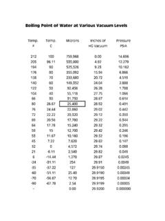
Transcription of OBTAINING TARGET SUPERHEAT VALUE …
1 A340001/4 SAE TEEW/SWIVELCOUPLERMATCHINGREFRIGERANTKEY TEMPERATURESENSORSUCTION LINELIQUID LINECONDENSINGUNITREFRIGERANTTANKTOSUCTI ON SERVICEVALVEQC RESTRICTORFITTINGTOLIQUID LINESERVICEVALVETEMPERATURESENSORSUPERHE ATSUBCOOLSUCTION LINELIQUID LINEMATCHINGREFRIGERANTKEYTEMPERATURESEN SORCONDENSING UNITTOLIQUIDSERVICEVALVETEMPERATURESENSO RSUPERHEATSUBCOOLSUCTION LINELIQUIDLINETEMPERATURESENSOREXPANSION VALVEMATCHINGREFRIGERANT KEYEVAPORATORTEMPERATURESENSORSUPERHEATS UBCOOL1. Connect the gauge to the A34000 tee fitting on the high (liquid) side of the manifold as the Temperature Sensor on the liquid line next to the liquid service valve and plug into system refrigerants other than R-22, plug in the matching Refrigerant Key into the the gauge display to show slowly add or remove refrigerant until the gauge displays the required Subcooling TESTSUCTION LINELIQUID LINEMATCHINGREFRIGERANTKEYTEMPERATURESEN SORCONDENSING UNITTOSUCTIONSERVICEVALVETEMPERATURESENS ORSUPERHEATSUPERHEATSUBCOOLING on the refrigerants other than R-22, plug in the matching Refrigerant Key.
2 TESTING FOR CHARGEEVAPORATORSUCTION in the Temperature Sensor and mount the sensor as the display to show SUPERHEAT or THE SUBCOOLING METHODAPPLICATIONS? Refrigeration Systems? High Efficiency Residential? Large Commercial A/C RooftopPackages Up To And Over 100 TonsAverage Subcooling VALUE is 10 12 .Contact manufacturer or wholesaler for specific With TXV And No Receiver OUTDOOR TEMP FEVAPORATORENTERINGAIR- 50 52 54 56 58 60 62 64 66 68 70 72 74 76 55 9 12 14 17 20 23 29 32 35 37 40 42 45 60 7 10 12 15 18 21 27 30 33 35 38 40 43 65 6 10 13 16 19 24 27 30 33 36 38 41 70 7 10 13 16 21 24 27 30 33 36 39 75 6 9 12 18 21 24 28 31 34 37 80 5 8 15 18 21 25 28 31 35 85 11 15 19 22 26 30 33 90 9 13 16 20 24 27 31 95 6 10 14 18 22 25 29 100 8 12 15 20 23 27 105 5 9 13 17 22 26 110 6 11 15 20 25 115 8 14 18 23 AWET BULB TEMPERATURE OF EVAPORATOR ENTERING on with zero pressure.
3 Gauge will automatically calibrate to Zero for altitude and atmospheric pressure the sock with water and slip on to sensor. Mount on the building return air grill or air return line of blower to measure the Indoor Wet Bulb Turn on the furnace fan to create a flow of air across the wet sock for 5 minutes. The final number will be your Wet Bulb sock and measure the Outdoor Air the outdoor temperature and evaporator entering air wet-bulb temperature on chart. The TARGET SUPERHEAT VALUE is at the intersection of the you have to do repairs, recheck your your connections and toggle the gauge to show SUPERHEAT . For system refrigerants other than R22, plug in matching Refrigerant slowly add or refrigerant to lower SUPERHEAT or remove refrigerant to raise SUPERHEAT until the gauge displays the TARGET TARGET SUPERHEAT VALUEJB INDUSTRIESAURORA, IL 60507 USAT echnical SUPERHEAT Chart(Located on condensing older models contact manufacturer)WETSOCKINAIRFLOWTEMPERATURE SENSORTEMPERATURESENSORSUCTION LINELIQUID LINEREFRIGERANTTANKTOSUCTION SERVICEVALVEQC RESTRICTORFITTINGTOLIQUID LINESERVICEVALVETEMPERATURESENSORA340001 /4 SAE TEEW/SWIVELCOUPLERMATCHINGREFRIGERANTKEY TEMPERATURESENSORSUPERHEATSUPERHEATSUPER HEATTARGET SUPERHEAT VALVESUPERHEATNot intended for use on hazardous or corrosive fluidsGAUGE SPECIFICATIONS:Pressure display range:29 InHg to 600 psig (-98kPa to 4134 kPa)(+/- 1 PSI to 200 psi, to 600 psi)Temperature display range: -40 F to 200 F (-40 C to 93 C)Operating temperature.
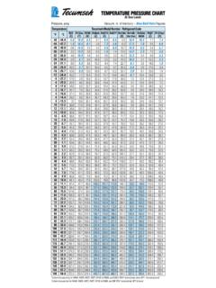
4 -10 F to 120 F (-12 C to 49 C)(+/- 1 F * 32 F/120 F, +/- F * -10 F/32 F)Maximum overpressure:800 psig (5512 kPa)Battery life and type:100 hours/ 9vAlkaline batteryAuto-shutoff time:60 minutes (extended 60 minutes by upper button action)Refrigerant data source:NIST REFRPRO software and manufacturers data Uses one 9v Alkaline battery (not included)EXTENDINGAUTO-SHUTOFF TIMEE xtend time by 60 minutes by pressing upper lower button 2 times to select 1 hour or 24 KEY (R410A Included)TEMPERATURESENSOR21R404 AHP62 PSI/FMANUFACTURER S DESIGNATION R NUMBERUNITS (F or C)Only a properly charged unit will provide the owner with the design SEER for maximum energy efficiency. SUPERHEAT , TEMPERATURE, SUBCOOLING AND PRESSUREPUSH once to toggle between displaysPUSH 2 times to recall High, Low & AverageHold down to clear once to Turn On Display shows LAST refrigerant down to "Turn Off"PUSH 2 times to select 1 hour or 24 hour auto-off modeREFRIGERANT SELECTIONPRESS once at any time to display current pressing to scroll the refrigerant list.
5 (See list of refrigerants on page 4.)Wait seconds, then continue pressing to reverse scroll TIPS:Allow the manifold to Zero at Turn-On:The manifold displays will zero (CAL) each time the manifold is turned on without pressure. Zeroing the gauge compensates the Pressure display for changes in (1) Altitude and (2) Barometric CalibrationDon t be alarmed if your manifold gauge does not agree with your mechanical gauges. The digital manifold is calibrated with a very accurate pressure and is not affected by vibration, motion or On-TimeThe digital manifold will turn off automatically after 60 minutes to save battery life. If any button is touched the digital manifold will stay on for another 60 IndicatorPressures or temperatures below or above the rated ranges will cause a 1 to be Battery IndicatorLow batteries will be indicated by a blinking For Low Temperature ApplicationsUsing the gauge in a low temperature conditions will shorten battery life.
6 Change to the 9 volt Lithium battery (Radio Shack 23-665) to solve this KEY PLUG-IN See page 4 for other refrigerant keys available. Metric and English keys are not ( F)and SH-36N( C) SUPERHEAT and SUBCOOLING GAUGEOPERATING INSTRUCTIONS REFRIGERATION APPLICATIONSSETTING FOR THERMOSTAT CONTROLLED CASES AND COOLERSW ithout plug-ins, turn on the gauge and zero the display by holding the lower button. Plug in the Temperature Sensor only and toggle to Temperature. SETTING FOR THERMOSTAT CONTROLLED CASES AND COOLERSW ithout plug-ins, turn on the gauge and zero the display by holding the lower button. Attempts to zero the gauge with pressure applied will result in (Err) & REFRIGERATION APPLICATIONSC ontact your TXV manufacturer for the exact SUPERHEAT adjust FTime in MinutesExpansionValve SuperheatSH-35N Average SuperheatHussmann RHFA 4 Door FF Case1 Ton LowTemp. TXV-2 F Case Temperature40% Heater LoadSET SUPERHEAT FOR HUNTING TXV VALUESIn refrigeration and air conditioning systems, the expansion valve often operates to produce an evaporator SUPERHEAT which constantly swings up and down in VALUE , called hunting.
7 The SH-35N provides the Average SUPERHEAT VALUE for TXV valve TXV SETTINGThe objectives of the TXV SUPERHEAT setting is to prevent liquid refrigerant floodback to the compresor and to optimize system operation by the use of a selected two temperature method of measuring SUPERHEAT is not recommended because it can produce a wrong SUPERHEAT measurement, due to the effect of temperature glide of the blended refrigerants and variations in evaporator pressure RESIDENTIAL A/C SYSTEMSFor new installations of residential A/C systems, the pre-charge will not provide an accurate amount of refrigerant charge because of the variation in the length of liquid and suction line connecting to the A SYSTEMSR etrofitting systems to a new refrigerant can change the TXV SUPERHEAT setting. The SUPERHEAT setting should be checked before and after retrofitting to be sure the SUPERHEAT is right for the ITEMSPART " QC x 1/4" Access Branch TeeSH-546' Temperature SensorSH-55 Plastic Carrying CaseSH-56 Socks (5)ACCESSORIESSH-5128' Temperature Sensor Extension KEY REFRIGERANT LIST A R11R12R13R22R23R134AR290R401AR401BR402AR 402BR403BR404AR406AR407AR408AR409AR410AR 411CR413AR414BR416AR417AR422AR500R502R50 7R508 BRB276 SUPERHEATJB in USAPart No.
8 10737-308 2006 J/B Industries and Celsius Keys are not interchangeableSUPERHEATTEMPERATURESENSO RTEMPPSIR407BR407CR422B