Transcription of APPLICATION AND ENGINEERING DATA Copper …
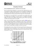
1 EXTRALONGLENGTHSCRITICALPOINT "L"OPTIMUMLENGTH RANGE5 to 16 LENGTHACTS LIKE ORIFICEOPTIMUM FLOWRANGEFLOWLENGTHCRITICAL POINT "S"Typical flow curve showingchanges in flow ofrefrigerant through acapillary tube with achange in the length of thecap size of the cap tube is fairly orifices, such as expansion valve seats,capillary tubes depend on their length as well astheir diameter to determine their total relationship between these two factors areshown in the following charts. A change indiameter on a percentage basis can change theflow more than an equal change in length.
2 Toillustrate, changing the diameter by .005" asbetween .026" and .031" can doublethe can also be changed by length-ening or shortening the cap tub. The longer thetube, the slower the flow; the shorter the tube, thefaster the flow. The general flow curve graph(right) shows what happens to the flow ofrefrigerant through a cap tube as the length ischanged. This curve is not meant to give specificflows but to simply illustrate what happens withall cap tubes so that the general flow pattern canbe following the flow curve from left to right itcan be seen that for the very longest length theflow is the smallest.
3 Then as the cap tube lengthis decreased, the flow increases slowly untilcritical point "L" is this point the flow increases more rapidlywith each reduction in length until critical point "S"is reached. From this point on, further decrease inDIAMETER AND LENGTHFACTORS AFFECTING REFRIGERANT FLOWAPPLICATION AND ENGINEERING DATAC opper Capillary TubingFor Refrigeration and Air-ConditioningSHORT COIL100 FT. COILS10 COILS ID x .072 OD x 16' ID x .083 OD x 12' ID x .087 OD x 12' ID x .093 OD x 12' ID x.
4 109 OD x 12' ID x .099 OD x 11' ID x .114 OD x 11' ID x .106 OD x 11' ID x .125 OD x 11' ID x .112 OD x 10' ID x .125 OD x 10' ID x .125 OD x 12' ID x .125 OD x 9' ID x .145 OD x 10' ID x .145 OD x 9' ID x .145 OD x 7' ID x .156 OD x 10'length causes ever increasing flow. From thestudy of this typical curve, certain pertinentconclusions can be reached that directly affectthe field APPLICATION of capillary the graph, the section above the criticalpoint "L" is marked as extra long to increase restriction ( reduceflow) by increasing length into this region is notonly uneconomical but frequently hopeless.
5 Inaddition, tubes in this range may not be respon-sive enough to changes in head pressures duringoperation. All in all, tube lengths in this rangeshould be avoided where down the graph, the sectionbelow critical point "S" should be avoided like theplague. In this range, the tube is so short thateven small changes in length will cause verylarge increases in flow. This is caused by the factthat the length no longer affects the flow and thetube now beings to act more like an orifice than acapillary tube. But, without the other componentsnecessary to control an orifice, such as arepresent in an expansion valve or high side float, avery short cap tube will give wildly erratic opera-tion under varying ambients and of this would be meaningless withoutsome definite way to use this information.
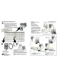
6 Al-though the critical points will vary depending onthe of the cap tubing being used, a very safeoperating rule-of-thumb can be offered. Keep thecap tube no shorter than 5 ft. and no longerthan 16 ft. COPYRIGHT 2007 J/B INDUSTRIES conversion chart enables the user to translatethe recommended length of tube diameter into sizesstocked by J/B. In using the chart it is recommendedthat conversions be made using factors within theunshaded USE CHART(1) Locate recommended cap tube in left handcolumn.(2) Read across and find conversion factor undercopper cap tube size.
7 (3) Multiply the given length of the recommended captube by the conversion TUBE LENGTH CONVERSION CHART(4) The resultant length (Min. 5 feet) ofcopper cap tube will give the same flow charac-teristics as the original recommended cap cap tube: 9' .040 .040 in left hand column and reading acrossgives the following conversion factor: No. TC-36(.62) and TC-42 ( ).Multiply the recommended cap tube length of 9'by the conversion factor gives the following results:5-1/2"-TC-36 and 11-1/4' TC-42. Either of thesetwo cap tubes will give the same results as theoriginal cap tube of 9'.
8 040 EVAPORTING TEMPERATURE DEGREES to +5+5 to +20+20 to +35+35 to +501/20R12S-F16 (2 pcs)1-1/2R22F7-1/2 (2 pcs)7-1/2 (2 pcs)8 (2 pcs))scp2( )scp2( )scp2( )scp2( (2 pcs)9 (2 pcs)10 (2 pcs))scp3( )scp3( (2 pcs)8 (4 pcs)10 (4 pcs))scp4( )scp4( )scp5( )scp5( )scp5( )scp5( : Condenser Type: S = Static, F = FANREFRIGERATION APPLICATION CHART (R-12 AND R-22)* TUBECIRCUITL engthSizeCIRCUITL engthSize400069 inTC-49875078 inTC-75425063 inTC-49900072 inTC-75450090 inTC-54925067 inTC-75475081 inTC-54950084 inTC-80500072 inTC-54975084 inTC-80525063 inTC-5410,00076 inTC-805500101 inTC-6410,25072 inTC-80575094 inTC-6410,50068 inTC-80600087 inTC-6410,75064 inTC-80625079 inTC-6411,00060 inTC-80650072 inTC-6411,25087 inTC-85675064 inTC-6411,50084 inTC-85700090 inTC-7011,75078 inTC-85725084 inTC-7012,00072 inTC-85750078 inTC-7012,50082 inTC-90775073 inTC-7013.
9 00072 inTC-90800069 inTC-7013,50066 inTC-90825064 inTC-7014,00060 inTC-90850084 inTC-75 Recommended capillary tube lengths for eachcircuit in an air conditioner evaporator where R-22 isthe refrigerant. All recommendations must beconsidered approximate and variations may arise inactual field air conditioners normally have 1 circuitand the recommended cap tube can be read directlyfrom the chart. Larger units have 2 or more circuits inthe evaporator. Where this is the case, simply dividethe total BTU rating of the unit by the number of captube circuits to obtain the BTU/CIRCUIT rating of eachindividual cap :Air conditioner is rated at 27,000 BTU and has 3 captubes connected to the evaporator.
10 Divide 27,000 by3 = 9,000 BTU/Circuit. From the chart, this would callfor .075 (TC-75) 72 inch length and any cap tube may be adjusted to a more readilyavailable size by using the conversion APPLICATION CHART (R-22)R-134a It is suggested to add 10% to length.*R-134a It is suggested to add 10% to service: 800-323-0811E-Mail: Site: in No. TC-803-308 REFRIGERATION REFERENCE CHART FOR CAPILLARY TUBINGFan Cooled Units Only. Add 10% to length for Static CooledSINGLE / R416A1/8TC-26110"TC-2684"TC-2648"1/6TC-2 671"TC-3196"TC-3172"1/5TC-3154"TC-3136"T C-3124"1/4TC-3143"TC-4290"TC-4260"1/3TC- 4293"TC-4272"TC-4236"1/2TC-4996"TC-4948" TC-6490"3/4TC-4960"TC-6492"TC-6472"1TC-4 936"TC-6484"TC-6454"1-1/2TC-6484"TC-6460 "TC-6443"2TC-6455"TC-6440"TC-6426"R134A / R401A / R401B / R406A.