Transcription of On-Premise Plus Instruction Manual
1 0901155 Rev: E (03/14) Page 1 of 16 On-Premise Plus Instruction Manual BLACKREDBROWNLMIBBLACKREDBROWNSIBPUMP #1 PUMP #2 PUMP #3 PUMP #4 PUMP #5 PUMP #6 SIGNAL INDICATORS*OPEN BOX SPLIT COMMONSBRNCOM B(-)(-)(+)(+)(+)(+)(+)(+)PUMP#6 PUMP#5 PUMP#4 PUMP#3 PUMP#2 PUMP#1 COM AYELORGBLUGRNREDWHTBLKSIGNALS 24-240V*BLKBLEACHDEFEATFORMULASELECTWHTR EDORGSWITCHES(TOGGLE)(MOMENTARY)Page 2 of 16 0901155 Rev: E (03/14) QUICK-REFERENCE Listed below is a guide for quickly setting features that are explained in detail throughout this Manual . As a reminder, you must have access (enter access code) to change any of the settings. Setting Formula # Pump # Range/Choice Access code A 1 0 255 Signal lockout time A 2 0 75 minutes Delay units A 3 1 = seconds 60 = minutes Pump 7 & 8 enable A 4 0 = disabled 1 = enabled Drain mode A 5 0 = disabled 1 = enabled Invert drain signal A 6 0 = normal 1 = inverted Levels disable A 7 0 = levels 1 = no levels System reset timer A 8 0 75 minutes Auto formula select time A A 0 = disabled 1 5 to select time Auto formula select mode A F 0 = micro 1 = chart * Formula disable Various F 0 = enable 1 = disable NOTE: The pump time LED must be flashing when setting all features above, except formula disable.
2 * Delay time LED must be flashing when setting the formula disable feature (only). CAUTION: The On-Premise Plus system has high voltage connected to the transformer. Always disconnect main power when servicing the unit. TABLE OF CONTENTS Quick-Start Programming .. 3 Introduction .. 4 Features .. 4 Pre-installation .. 5 Installation .. 5 Operating Modes .. 6 Programming .. 7 Load Counts .. 10 Drain Mode .. 11 Other Features .. 12 Troubleshooting .. 14 System Wiring Diagram .. 15 Warranty Information .. 16 Knight Locations .. 16 0901155 Rev: E (03/14) Page 3 of 16 QUICK-START PROGRAMMING The steps below will give you just the basics to quickly setup a new system more details and complete programming information are included in the following pages of this Manual .
3 (1) Press once (for default 000 access code). (2) Press ACC will flash briefly on the display. You now have access. (3) Note that the pump time LED will be flashing. (4) Press pump SELECT until desired pump number is displayed. NOTE: If using a flush manifold, program pump F on all formulas to set flush time. (5) Press formula SELECT until desired formula number appears. (6) Use / to input the pump time or flush time (or delay time) in seconds. (7) Press display will flash indicating that your entry has been saved. (8) To program a pump delay time, press MODE until delay time LED is flashing. Repeat steps 4 7. (9) To set the load count pump, press ENTER twice (note that pump time & delay time LED s turn off). Use pump SELECT to choose the pump number that will be used to count loads for each formula.
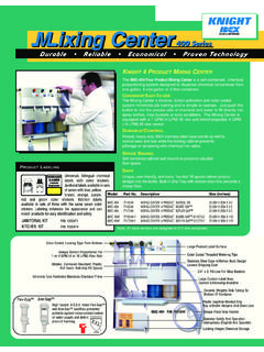
4 After a few seconds, the pump time LED will return, indicating that your entry has been saved. (10) Press RESET when finished programming and ready to run. 1 4 5 9 2 7 10 3 8 6 Page 4 of 16 0901155 Rev: E (03/14) INTRODUCTION The On-Premise Plus was designed to meet today s laundry chemical injection needs with economy and flexibility in mind. Advanced microprocessor technology makes the OP-Plus one of Knight s least expensive laundry injectors, yet has all the features to meet every type of On-Premise laundry condition. The On-Premise Plus is a three component system, with each component performing a specific function. See diagram below for illustration of the following: (1) The Signal Interface Module (SIB) receives supply signals from the washmachine.
5 (2) Signals are routed to the Remote Control which controls all timing and programming functions. Pump run times and delay times are activated for the selected formula number. (3) The output circuit board located inside the pump cabinet then runs the pumps for the correct amount of time. Components utilize Plug & Play connections for easy installation. FEATURES 8 formula capability for various soil conditions Independent pump run times to provide specific volume injections Individual delay times for all wash formulas gives greater flexibility with fixed timer washwheels All programmed data is stored in a non-volatile memory which cannot be altered by voltage spikes or power outages. Optional Drain Mode and Relay Mode Optional Auto Formula Select Formula and level enable/disable capability Flush mode can be used with all modes of operation Optional case mount flush manifold with solenoid provides single line diluted chemical injection LED display on the remote control let the user know which pump is running, and which formula is active The signal input circuitry will accept and verify a signal that is in the range of 24 to 240 volts.
6 1 3 2 BLACKREDBROWNLMIBBLACKREDBROWNSIBPUMP #1 PUMP #2 PUMP #3 PUMP #4 PUMP #5 PUMP #6 SIGNAL INDICATORS*OPEN BOX SPLIT COMMONSBRNCOM B(-)(-)(+)(+)(+)(+)(+)(+)PUMP#6 PUMP#5 PUMP#4 PUMP#3 PUMP#2 PUMP#1 COM AYELORGBLUGRNREDWHTBLKSIGNALS 24-240V*BLKBLEACHDEFEATFORMULASELECTWHTR EDORGSWITCHES(TOGGLE)(MOMENTARY)0901155 Rev: E (03/14) Page 5 of 16 CUT RESISTOR TO USE COM A FOR PUMPS AND COM B FOR PUMPS R2 1, 2 3, 4, 5, 6 R1 1, 2, 3 4, 5, 6 R4 1, 2, 3, 4, 5 6 PRE-INSTALLATION Before the equipment is installed, you should survey the installation site thoroughly. At the very least, your survey should include the following: Check to make sure that all functions of the washmachine are operating properly. Including; card reader or timer, water solenoids, flush down valves, water level switch, machine motor, and drain valve.
7 Check the proposed location for a 115, 208, or 230 VAC power source. Check voltage of all supply signals that will be used from the washmachine. Measure voltage between supply signal and signal common with a voltmeter. DO NOT check signal voltage between supply signal and case (earth) ground. Measure the distance from chemical supply containers to pump housing, and from pump housing to injection point inside washmachine. INSTALLATION (1) Disconnect all power to washer. (2) Mount pump cabinet in a convenient location no higher than 8 above, and within 10 horizontally, of supply containers. This is usually near the washer, however dispenser can be mounted as a remote pumping system. (3) Using the provided mounting bracket, mount the Remote Control to the front of the washer where operators can easily access it.
8 Secure the bracket to washer using provided mounting screws or Dual-Lock fastening strips (be sure to first clean the mounting surface as the adhesive will not stick to a dirty surface). Connect the low voltage cable from the remote to the pump cabinet. (4) Connect 115, 208, or 230 VAC power source to main power connection in pump cabinet. Use suitable conduit for electrical wiring (per applicable wiring codes). NOTE: Low voltage Plug & Play cables do not require conduit. (5) Install and wire the Signal Interface Module (SIB) per notes to the right. (6) For each pump, cut the suction tube to length and insert one end into the appropriate supply container using PVC pipe as a support. Insert other end of suction tube into the left (input) side of the pump s squeeze tube.
9 (7) For each pump, cut the discharge tube to length and insert one end into the right (output) side of the pump s squeeze tube. Form an anti-siphon loop (pointing down ) with the other end of discharge tube and insert into the supply pocket of the machine. (8) The system is now ready to be powered up and programmed. The Signal Interface Module (SIB): The SIB receives supply signals from the washer, then communicates with the dispenser to run the pumps. The low voltage Plug-n-Play cable allows a quick, clean connection from the module to the pump system without requiring conduit. (1) Mount the module using the provided Dual Lock adhesive strip. The module can be mounted inside the washer s controls, along side the washer s controls, or to the bottom of the pump cabinet.
10 (2) Connect the low voltage cable from the module to the OP-Plus pump system. (3) Connect the supply signals to the SIB per wire colors on the SIB label. If using Drain Mode, only one signal is required (pump #1). (4) If you have one signal common (typical) connect the common to COM A on the SIB. If you have two signal commons, you will need to remove a resistor inside the SIB before connecting the common wires! See the following details. Splitting signal commons: (1) Remove the four screws from the bottom of the SIB to open the module. (2) Locate the three resistors marked R1, R2, and R4, on the left side of the module (each resistor has a single black band). (3) Cut and remove the resistor that will split the commons between the desired pumps.