Transcription of OPA381 OPA2381 Precision, Low Power, 18MHz ... - TI.com
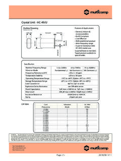
1 FEATURESDOVER 250kHz TRANSIMPEDANCEBANDWIDTHDDYNAMIC RANGE: 5 DecadesDEXCELLENT LONG-TERM STABILITYDLOW VOLTAGE NOISE: 10nV/ HzDBIAS CURRENT: 3pADOFFSET VOLTAGE: 25 V (max)DOFFSET DRIFT: V/ C (max)DGAIN BANDWIDTH: 18 MHzDQUIESCENT CURRENT: 800 ADFAST OVERLOAD RECOVERYDSUPPLY RANGE: to AND DUAL VERSIONSDM icroPACKAGE: DFN-8, MSOP-8 APPLICATIONSDPRECISION I/V CONVERSIONDPHOTODIODE MONITORINGDOPTICAL AMPLIFIERSDCAT-SCANNER FRONT-ENDDPHOTO LAB EQUIPMENT1M RF100k +5V72346 OPA38165pF75pFCDIODE 5 VRP(OptionalPulldownResistor)VOUT(0V to )PhotodiodeDESCRIPTIONThe OPA381 family of transimpedance amplifiers provides18 MHz of Gain Bandwidth (GBW), with extremely highprecision, excellent long-term stability, and very low 1/f OPA381 features an offset voltage of 25 V (max), offsetdrift of V/ C (max), and bias current of 3pA. The OPA381far exceeds the offset, drift, and noise performance thatconventional JFET op amps signal bandwidth of a transimpedance amplifier dependslargely on the GBW of the amplifier and the parasiticcapacitance of the photodiode, as well as the feedbackresistor.
2 The 18 MHz GBW of the OPA381 enables a trans-impedance bandwidth of > 250kHz in most OPA381 is ideally suited for fast control loops for powerlevel measurement on an optical a result of the high precision and low-noise characteristicsof the OPA381 , a dynamic range of 5 decades can beachieved. This capability allows the measurement of signalcurrents on the order of 10nA, and up to 1mA in a single I/Vconversion stage. In contrast to logarithmic amplifiers, theOPA381 provides very wide bandwidth throughout the fulldynamic range. By using an external pulldown resistor to 5V, the output voltage range can be extended to include OPA381 and OPA2381 are both available in MSOP-8and DFN-8 (3mm x 3mm) packages. They are specifiedfrom 40 C to +125 RELATED DEVICESPRODUCTFEATURESOPA38090 MHz GBW, to SupplyTransimpedance AmplifierOPA13216 MHz GBW, Precision FET Op Amp 15 VOPA300150 MHz GBW, Low-Noise, to SupplyOPA33510 V VOS, Zero-Drift, to 5V SupplyOPA350500 V VOS, 38 MHz, to 5V SupplyOPA354100 MHz GBW CMOS, RRIO, to 5V SupplyOPA355200 MHz GBW CMOS, to 5V SupplyOPA656/7230 MHz, Precision FET, 5 VOPA381 OPA2381 SBOS313B AUGUST 2004 REVISED NOVEMBER 2004 Precision, Low Power, 18 MHzTransimpedance Amplifier !
3 ! 2004, Texas Instruments IncorporatedAll trademarks are the property of their respective be aware that an important notice concerning availability, standard warranty, and use in critical applications of Texas Instrumentssemiconductor products and disclaimers thereto appears at the end of this data sheet. "#$ %"#$ SBOS313B AUGUST 2004 REVISED NOVEMBER MAXIMUM RATINGS(1)Voltage Supply+7V.. Signal Input Terminals(2), Voltage(V ) to (V+) + .. Current 10mA.. Short-Circuit Current(3)Continuous.. Operating Temperature Range 40 C to +125 C.. Storage Temperature Range 65 C to +150 C.. Junction Temperature+150 C.. Lead Temperature (soldering, 10s)+300 C.. OPA381 ESD Rating (Human Body Model)2000V.. OPA2381 ESD Rating (Human Body Model)1500V.. (1)Stresses above these ratings may cause permanent to absolute maximum conditions for extended periodsmay degrade device reliability.
4 These are stress ratings only, andfunctional operation of the device at these or any other conditionsbeyond those specified is not implied.(2)Input terminals are diode clamped to the power-supply rails. Inputsignals that can swing more than beyond the supply railsshould be current limited to 10mA or less.(3)Short-circuit to ground; one amplifier per DISCHARGE SENSITIVITYThis integrated circuit can be damaged by ESD. TexasInstruments recommends that all integrated circuits behandled with appropriate precautions. Failure to observeproper handling and installation procedures can cause damage can range from subtle performance degradation tocomplete device failure. Precision integrated circuits may be moresusceptible to damage because very small parametric changes couldcause the device not to meet its published INFORMATION(1)PRODUCTPACKAGE-LEADPACKAGE DESIGNATORSPECIFIEDTEMPERATURERANGEPACKA GEMARKINGORDERINGNUMBERTRANSPORTMEDIA, QUANTITYOPA381 MSOP-8 DGK 40 C to +125 CA64 OPA381 AIDGKTTape and Reel, 250 OPA381 MSOP-8 DGK 40 C to +125 CA64 OPA381 AIDGKRTape and Reel, 2500 OPA381 DFN-8 DRB 40 C to +125 CA65 OPA381 AIDRBTTape and Reel, 250 OPA381 DFN-8 DRB 40 C to +125 CA65 OPA381 AIDRBRTape and Reel, 3000 OPA2381 MSOP-8 DGK 40 C to +125 CA62 OPA2381 AIDGKTTape and Reel, 250 OPA2381 MSOP-8 DGK 40 C to +125 CA62 OPA2381 AIDGKRTape and Reel, 2500 OPA2381 DFN-8 DRB 40 C to +125 CA63 OPA2381 AIDRBTTape and Reel, 250 OPA2381 DFN-8 DRB 40 C to +125 CA63 OPA2381 AIDRBRTape and Reel, 3000(1)
5 For the most current package and ordering information, see the Package Option Addendum located at the end of this data ASSIGNMENTSDFN 8 Top View12348765NC(1)V+OutNC(1)NC(1) In+InV OPA381 MSOP 812348765V+Out B In B+In BOut A In A+In AV OPA2381 MSOP 812348765NC(1)V+OutNC(1)NC(1) In+InV OPA381 ExposedThermalDie PadonUnderside12348765V+Out B In B+In BOut A In A+In AV OPA2381 ExposedThermalDie PadonUndersideDFN 8 NOTE: (1) NC indicates no internal connection. "#$ %"#$ SBOS313B AUGUST 2004 REVISED NOVEMBER CHARACTERISTICS: VS = + to + Boldface limits apply over the temperature range, TA = 40 C to +125 specifications at TA = +25 C, RL = 10k connected to VS/2, and VOUT = VS/2, unless otherwise VOLTAGEI nput Offset VoltageVOSVS = +5V, VCM = 0V725 V/ Cvs Power SupplyPSRRVS = + to + , VCM = V/VOver TemperatureVS = + to + , VCM = 0V20 V/VLong-Term Stability(1)See Note (1)Channel Separation, dc1 V/VINPUT BIAS CURRENTI nput Bias CurrentIB VCM = VS/23 50pAOver TemperatureSee Typical CharacteristicsInput Offset CurrentIOS VCM = VS/26 100pANOISEI nput Voltage Noise, f = to 10 HzenVS = +5V, VCM = 0V3 VPPI nput Voltage Noise Density, f = 10kHzenVS = +5V, VCM = 0V70nV/ HzInput Voltage Noise Density, f > 1 MHzenVS = +5V, VCM = 0V10nV/ HzInput Current Noise Density, f = 10kHzinVS = +5V, VCM = 0V20fA/ HzINPUT VOLTAGE RANGEC ommon-Mode Voltage RangeVCM V (V+)
6 Rejection RatioCMRRVS = +5V, (V ) < VCM < (V+) IMPEDANCED ifferential Capacitance 1pFCommon-Mode Resistance and Capacitance1013|| || pFOPEN-LOOP GAINOpen-Loop Voltage < VO < (V+) , VCM = VS/2, VS = 5V110135dB0V < VO < (V+) , VCM = 0V, RP = 10k to 5V(2), VS = 5V106135dBFREQUENCY RESPONSEGain-Bandwidth ProductGBW 18 MHzSlew RateSRG = +112V/ sSettling Time, (3)VS = +5V, 4V Step, G = +1, OPA3817 sSettling Time, (3)VS = +5V, 4V Step, G = +1, OPA23817 sOverload Recovery Time(4), (5)VIN G = > VS200nsOUTPUTV oltage Output Swing from Positive RailRL = 10k 400600mVVoltage Output Swing from Negative RailRL = 10k 3050mVVoltage Output Swing from Positive RailRP = 10k to 5V(2)400600mVVoltage Output Swing from Negative RailRP = 10k to 5V(2) 200mVOutput CurrentIOUT10mAShort-Circuit CurrentISC20mACapacitive Load DriveCLOADSee Typical CharacteristicsOpen-Loop Output ImpedanceROF = 1 MHz, IO = 0250 POWER SUPPLYS pecified Voltage Current (per amplifier)IQIO = RANGES pecified and Operating Range 40+125 CStorage Range 65+150 CThermal ResistanceqJAMSOP-8150 C/WDFN-865 C/W(1)High temperature operating life characterization of zero-drift op amps applying the techniques used in the OPA381 have repeatedly demonstrated randomlydistributed variation approximately equal to measurement repeatability of 1 V.
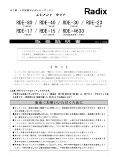
7 This consistency gives confidence in the stability and repeatability of these zero-drift techniques.(2)Tested with output connected only to RP, a pulldown resistor connected between VOUT and 5V, as shown in Figure 3. See also Applications section, AchievingOutput Swing to Negative Rail.(3)Transimpedance frequency of 250kHz.(4)Time required to return to linear operation.(5)From positive rail. "#$ %"#$ SBOS313B AUGUST 2004 REVISED NOVEMBER CHARACTERISTICS: VS = + to + All specifications at TA = +25 C, RL = 10k connected to VS/2, and VOUT = VS/2, unless otherwise 20 OPEN LOOP GAIN AND PHASE vs FREQUENCYF requency (Hz)Open Loop Gain (dB)200150100500 50 100 150 200 Phase (_)10100k1M1001k10k100M10 MPhaseGain140120100806040200 20 40 60 POWER SUPPLY REJECTION RATIO ANDCOMMON MODE REJECTION vs FREQUENCYF requency (Hz)PSRR, CMRR (dB)10100k1M1001k10k100M10 MPSRRCMRR908070605040302010 PHASE MARGIN vs LOAD CAPACITANCECLLoad Capacitance (pF)Phase Margin (_)0100 200 300 400 500 600 7009008001000RS=100 RS=50 RS=0 50k CURRENT vs TEMPERATUREQ uiescent Current (mA) (_C) 40100125 250255075 QUIESCENT CURRENT vs SUPPLY VOLTAGES upply Voltage (V) Current (mA)1000100101 INPUT BIAS CURRENT vs TEMPERATURET emperature (_C)Input Bias Current (pA)
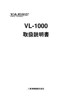
8 40100125 250255075 "#$ %"#$ SBOS313B AUGUST 2004 REVISED NOVEMBER CHARACTERISTICS: VS = + to + (continued)All specifications at TA = +25 C, RL = 10k connected to VS/2, and VOUT = VS/2, unless otherwise BIAS CURRENTvs COMMON MODE VOLTAGEC ommon Mode Voltage (V) IB+ 10 20 30 40 50 Input Bias Current (pA)OUTPUT VOLTAGE SWING vs OUTPUT CURRENT(VS= )Output Swing (V)5101520250 Output Current (mA)(V+)(V+) 1(V+) 2(V )+2(V )+1(V ) 40_C+125_C+25 COUTPUT VOLTAGE SWING vs OUTPUT CURRENT(VS= )Output Swing (V)5 101520250(V+)(V+) (V+) (V+) (V+) (V ) + (V ) + (V ) + (V ) + (V )Output Current (mA)+125_C 40_C+25_COFFSET VOLTAGE DRIFTPRODUCTION DISTRIBUTIONO ffset Voltage Drift ( V/_C)Population VOLTAGE PRODUCTION DISTRIBUTIONO ffset Voltage ( V)Population BANDWIDTH vs POWER SUPPLY VOLTAGEGain Bandwidth (MHz) Supply Voltage (V) "#$ %"#$ SBOS313B AUGUST 2004 REVISED NOVEMBER CHARACTERISTICS.
9 VS = + to + (continued)All specifications at TA = +25 C, RL = 10k connected to VS/2, and VOUT = VS/2, unless otherwise forTransimpedance Amplifier Characteristiccurves on this AMP CHARACTERISTIC10015014013012011010090807 06050403020101k10k100k1M10M100 MFrequency (Hz)Transimpedance Gain (V/A in dB)RF=10M CDIODE= 100pFCF= CF=1pFRF= 100k CF= 4pFRF=10k CF=12pFCSTRAY(parasitic) = AMP CHARACTERISTIC10015014013012011010090807 06050403020101k10k100k1M10M100 MFrequency (Hz)Transimpedance Gain (V/A in dB)RF=10M CDIODE= 50pFRF=1M CF=1pFRF= 100k CF= 3pFRF=10k CF=8pFCSTRAY(parasitic) = AMP CHARACTERISTIC1001k10k100k1M10M100 MFrequency (Hz)Transimpedance Gain (V/A in dB)15014013012011 0100908070605040302010 CSTRAY(parasitic) = 20pFRF= 10M RF=1M CF= CF=2pFRF= 10k CF=5pFTRANSIMPEDANCE AMP CHARACTERISTIC1001k10k100k1M10M100 MFrequency (Hz)Transimpedance Gain (V/A in dB)150140130120110100908070605040302010 CDIODE= 10pFCSTRAY(parasitic) = 10M RF=1M CF= CF=2pFRF= 10k CF=4pFTRANSIMPEDANCE AMP CHARACTERISTIC1001k10k100k1M10M100 MFrequency (Hz)Transimpedance Gain (V/A in dB)15014013012011 0100908070605040302010 CSTRAY(parasitic) = 10M RF=1M RF=100k RF= 10k CF= 2pF "#$ %"#$ SBOS313B AUGUST 2004 REVISED NOVEMBER CHARACTERISTICS.
10 VS = + to + (continued)All specifications at TA = +25 C, and RL = 10k connected to VS/2, unless otherwise SIGNAL STEP RESPONSE(with or without pull down)50mV/divTime (100ns/div)50k 10k CFVP200kHz (CF= 16pF)1 MHz(CF= 3pF)VP=0 Vor 5 VOPA381 LARGE SIGNAL STEP RESPONSE(with pull down)1V/divTime (100ns/div)50k 10k 3pF 5 VOPA381 LARGE SIGNAL STEP RESPONSE(without pull down)Time (100ns/div)1V/div50k 10k CF1 MHz(CF=3pF)200kHz(CF=16pF) OPA381 OVERLOAD RECOVERYTime (ns) (V/div)IIN(mA/div)0100 200 300 400 500 600 700 800 900 1000 VOUT20k 10k IINVP40pF250 AIINN onlinearOperationLinearOperationOPA381 OPA2381VP=0 Vor 5 VOPA3811000100101 INPUT VOLTAGE NOISE SPECTRAL DENSITYF requency (Hz)Input Voltage Noise (nV/ (Hz)10100100k1M10k1k10 MCHANNEL SEPARATION vs INPUT FREQUENCYI nput Frequency (Hz)160140120100806040200 20 40 Channel Separation (dB)101001k10k100k1M10M100 MOPA2381 "#$ %"#$ SBOS313B AUGUST 2004 REVISED NOVEMBER INFORMATIONBASIC OPERATIONThe OPA381 is a high-precision transimpedanceamplifier with very low 1/f noise.)