Transcription of Orthographic Projections
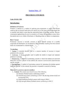
1 Orthographic . Projections . ME111. By Dr. Akhilesh Kumar Maurya Orthographic Projections Orthographic Projections is a technical drawing in which different views of an object are projected on different reference planes observing perpendicular to respective reference plane. Different Reference planes are;. Horizontal Plane (HP). Vertical Plane (VP). Side or Profile Plane (PP). Different views are;. Front View (FV) Projected on VP. Top View (TV) Projected on HP. Side View (SV) Projected on PP. NOTATIONS. Following notations should be followed while naming Different views in Orthographic Projections .
2 OBJECT POINT A LINE AB. IT'S TOP VIEW a ab IT'S FRONT VIEW a a b . IT'S SIDE VIEW a a b . Same system of notations should be followed incase numbers, like 1, 2, 3 are used. TERMS ABOVE' & BELOW' WITH RESPECT TO AND TERMS INFRONT' & BEHIND' WITH RESPECT TO 3. Types of views Projections Parallel Converge Orthogonal Oblique Multiview Axonometric Multi-view drawing Pictorial drawing Perspective drawing View comparison Type Advantage Disadvantage Multi-view drawing Accurately presents Require training object's details, to visualization.
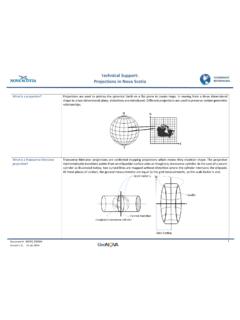
3 Size and shape. Pictorial drawing Easy to visualize. Shape and angle distortion Circular hole becomes ellipse Right angle becomes obtuse angle. Perspective drawing Object looks more Difficult to create like what our eyes Size and shape perceive. distortion Distorted width PLANES. PRINCIPAL PLANES. HP AND VP. AUXILIARY PLANES. Auxiliary Vertical Plane Auxiliary Inclined Plane Profile Plane ( ) ( ) ( ).. to Hp & to Vp . PATTERN OF PLANES & VIEWS (First Angle Method). THIS IS A PICTORIAL SET-UP OF ALL THREE PLANES.
4 ARROW DIRECTION IS A NORMAL WAY OF OBSERVING THE OBJECT. BUT IN THIS DIRECTION ONLY VP AND A VIEW ON IT (FV) CAN BE SEEN. THE OTHER PLANES AND VIEWS ON THOSE CAN NOT BE SEEN. PROCEDURE TO SOLVE ABOVE PROBLEM:- TO MAKE THOSE PLANES ALSO VISIBLE FROM THE ARROW DIRECTION, A) HP IS ROTATED 900 DOUNWARD. B) PP, 900 IN RIGHT SIDE DIRECTION. THIS WAY BOTH PLANES ARE BROUGHT IN THE SAME PLANE CONTAINING VP. Click to view Animation On clicking the button if a warning comes please click YES to continue, this program is safe for your pc.
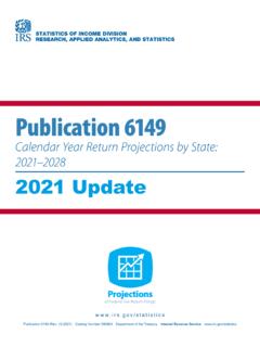
5 VP PP. Y. FV LSV. X Y. X TV. HP. ACTUAL PATTERN OF PLANES & VIEWS. HP IS ROTATED DOWNWARD 900 PP IS ROTATED IN RIGHT SIDE 900 OF Orthographic Projections . AND AND DRAWN IN. BROUGHT IN THE PLANE OF VP. BROUGHT IN THE PLANE OF VP. FIRST ANGLE METHOD OF Projections . projection systems 1. First angle system - European countries First - ISO standard quadrant 2. Third angle system - Canada, USA, Japan, Thailand Transparent Opaque planes planes Third quadrant Orthographic views 1st angle system 3rd angle system (Opaque planes) (transparent planes/glass box).
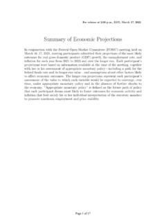
6 Orthographic views 1st angle system 3rd angle system Folding line Folding line Folding line Folding line Views arrangement 1st angle system 3rd angle system Top View Right Side View Front View Front View Right Side View Top View projection symbols 1st angle system 3rd angle system d Methods of Orthogonal projection 1. Natural Method: Revolve the object with respect to observer 2. Glass box method: The observer moves around the object. Glass box concept Top view Top view Front Right side view Front view Right side view play view play Glass box : Revolution of the planes of projection Rear view Left side view Bottom view Relative orientation of views Depth Width Height Summary : Problem solving steps Given 1 2.
7 3 4. Steps for Orthographic Views 152. 64 Top 1. Select the necessary views 25~4. 0. 45 Front 2. Layout the selected views 152. on a drawing Choose a drawing scale sheet. (say 1:1). 3. Complete each x x selected views. z y Top 4. Complete the dimensions and y x x notes. Front y y View selection procedures 1. Orient the object to the best position relative to a glass box. 2. Select the front view. 3. Select adjacent views. Suggestions: Orient the object 1. The object should be placed in its natural position.
8 2. The Orthographic views should represent the true size and true shape of an object (as much as possible). GOOD NO ! Suggestions: Select the front view 1. The longest dimension of an object should be presented as a width (in a front view). First choice Inappropriate Second choice Good Use more space Suggestions: Select the front view 2. The adjacent views project from the selected front view should be appeared in a natural position. Inappropriate Suggestions: Select the front view 3. It has the fewest number of hidden lines.
9 Good Inappropriate Suggestions: Select an adjacent view 1. Choose the view that has the fewest number of hidden lines. Inappropriate Inappropriate Suggestions: Select an adjacent view 2. Choose the minimum number of views that can represent the major features of the object. All information is placed on a single view. Necessary Hole's information is placed on a separated view. Necessary Suggestions: Select an adjacent view 3. Choose the views that are suitable to a drawing sheet. Poor Not enough space for dimensioning.
10 Choose another adjacent view. Good Change orientation of the Good selected views. Summary View selection has 3 steps Orient Select Select the object front view adjacent views Object that requires only one-view Flat (thin) part having a uniform thickness such as a gasket, sheet metal etc. Cylindrical-shaped part. Example 1 Thick Adjacent views provide only a part's thickness ! Object that requires only one-view Flat (thin) part having a uniform thickness such as a gasket, sheet metal etc. Cylindrical-shaped part.