Transcription of Outboard Motor Tachometer IS0012 - Faria Beede
1 Disconnect the battery during installation. Tighten nuts on the backclamp only slightly more than you can tighten with your fingers. Six inch-pounds of torque is sufficient. Overtightening may result in damage to the instrument and may void your Location: The Tachometer should be located at least 18 from a magnetic compass. Some interference (erratic operation) may be noticed on the Tachometer during radio transmissions. This will neither damage a Tachometer nor affect accuracy when not Be certain to use stranded, insulated wire not lighter than 18 AWG that is approved for marine use.
2 It is recommended that insulated wire terminals, preferably ring type, be used on all connections to the tach, except the light, which requires a 1/4 insulated female blade terminal. 3. Using a small flat head screw driver, SLIGHTLY depress and turn the selector switch on the back of the Tachometer to the correct position to match the number of poles in the alternator (see label on the side of the Tachometer ). Depressing the switch too hard may cause damage to the Tachometer !
3 Be sure the selector switch has locked into the Standard Case5. Connect a wire to the tach stud marked BAT (battery) and secure with a nut and lock washer. Connect the opposite end to a 12 VDC circuit that is activated by the ignition switch. 6. Connect a wire to the tach stud marked SIG (signal) and secure with a nut and lock washer. Connect the opposite end to a terminal or wire originating from the unrectified side of the alternator. On most late model outboards , a tach hook-up wire can be found at the control box.
4 Tach plug-in harnesses are sometimes available from the engine manufacturer to simplify the Connect a wire to the tach stud marked GND (ground) and secure with a nut and lock washer. Connect opposite end to the boat s electrical ground, generally available in several locations at or near the instrument Connect the blade terminal adjacent to the twist-out light assembly to the positive + side of the boat s instrument lighting circuit. No separate ground is required for lighting.
5 Connectorized Case5. Insert a wire with appropriate contact to the Tachometer Signal function of the connector. Connect the opposite end to the terminal or wire originating from the unrectified side of the alternator. On most late model outboards , a Tachometer hookup wire can be found at the control box. Tachometer plug-in harnesses are sometimes available from the engine manufacturer to simplify the Insert a wire with the appropriate contact to the + (positive) function of the connector.
6 Connect the opposite end to a 12 Vdc circuit that is activated by the ignition Insert a wire with appropriate contact to the ground function of the connector. Connect the opposite end to the boat s electrical ground, generally available in several locations at or near the instrument Insert a wire with appropriate contact to the light function of the connector. Connect the opposite end to the positive portion of the lighting circuit. Insert the connector into the back of the case. 9. Reconnect the To change light bulb, twist black socket assembly one-eighth turn counter clockwise until it pops out.
7 Bulb pulls straight out of assembly. Use a GE No. 194 instrument lamp for If your Tachometer is equipped with an hourmeter, the hourmeter will be energized only while the engine is running. Outboard Motor Tachometer & Tachometer with HourmeterIS0012 Rev. AC ecn 10592 6/2017 CautionMade in the USAI nstallationWire ConnectionsReconnect PowerFaria Beede Instruments, at the correct position by slightly rotating the switch back and forth with the screwdriver. If the number of poles is not known, consult the Outboard Tachometer Application chart or call Faria Beede Instruments at (860) 848-9271 with make, model, HP, and year of the Motor .
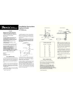
8 Note: If a fine adjustment is required, use a 000 Phillips Jewelers screw driver through the Fine Adjustment Pot access hole. (Some older model tachometers may required a 5/64 allen wrench.) 4. Cut a 3-3/8 (for 4 Tachometer or 4 3/8 for 5 ) diameter hole in the dash and mount the Tachometer with the backclamp supplied. For connectorized cases be sure to cut a .175 wide by .115 deep notch to accept the key on the case. See Detail A on next to next page for diagrams of wire ConnectorPackard ConnectorHookup Function Hookup Function + Positive + Positive L ights L ights TN/CN/Cachometer Signal Ground Tachometer Signal Ground Connector DT06-6S Connector 12162189 Contact 1062-16-0122 Contact 12124075 Wedge L ock W6S Plug 12034413 Plug 114017 For technical assistance, contact Faria Beede Instruments - Customer Service between 8:30 AM and 5.
9 30 PM Eastern time weekdays at (860) 848-9271 or (800) 473-2742. 3-3/8 Connector CaseIS0012 Standard Case - Wire diagramConnectorized Case - Wire diagramFine Adjustment PotEngine Running Only hourmeters by Faria Beede have an icon in the left hand corner of the display. The icon lets the operator know that hours are being displayed. During normal operations the icon displays solid when the key is on and the engine has not yet been started. Turning the engine on activates the counting function. The icon will begin to blink indicating that the hourmeter is currently counting hours for the connected engine.
10 This is Running Only HourmetersIconTachometer ApplicationsReference IS0086 Rev. V ecn 10430 8/2016 Notes:a. 6000 RPM tachs are for Inboard & I/O gas engine applications onlyb. 7000 RPM & 8000 RPM tachs are for all Outboard Motor applications only. 20 Pole Tachs are no longer Electrical pulses per revolution are equal to 1/2 the number of alternator Older model outboards (prior to 1977) may have the tach signal wire originating at the ignition system though they are alternator equipped. All alternator tachometers may be used on these systems by disconnecting the tach signal wire at the engine and connecting that ENG.