Transcription of Installation Instructions 4-in-1 Gauge
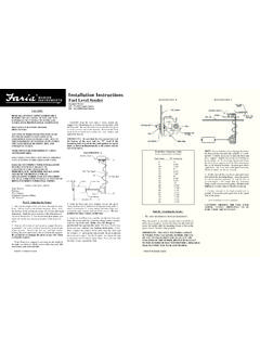
1 IS0092B ECR2951 10/2002 CAUTION: Disconnect the battery duringinstallation. Tighten nuts on the backclamp onlyslightly more than you can tighten with your inch-pounds of torque is sufficient. may result indamage to the instrument and may void your Be certain to use stranded, insulated wire not lighterthan 18 AWG that is approved for marine use. It isrecommended that insulated wire terminals, preferablyring type, be used on all Cut a 3-3/8 dia. hole in the dash and mount thegauge with the backclamp Connect a wire to the stud marked 4 (ground) andsecure with a nut and lockwasher. Connect oppositeend to the boat s electrical ground, generally availablein several locations at or near the instrument Connect a wire to the stud marked 7 (B+) andsecure with a nut and lockwasher.
2 Connect theopposite end to a 12 VDC circuit that is activated by theignition Connect a wire to the stud marked 1 (lights).Connect the opposite end to the positive + side ofthe boat s instrument lighting circuit. No separateground is required for Connect a wire to the stud marked 6 ( fuel send.)and secure with a nut and lockwasher. Connect theopposite end to the to the stud on the sensing unit andsecure with a nut and Connect a wire to the stud marked 3 (temp. send.)and secure with a nut and lockwasher. Connect theopposite end to the to the stud on the sensing unit andsecure with a nut and Connect a wire to the stud marked 5 (oil send.)and secure with a nut and lockwasher. Connect theopposite end to the to the stud on the sensing unit andsecure with a nut and Be certain wire insulation is not in danger of melting from engine exhaust heat or interfering with moving mechanical parts when connecting to sensors.
3 * NOTE: Stud functions are different for the 5 inch Gauge and are as follows: 1 (ground), 3 (lights), 4 ( fuel send.), 5 (temp send.), 6 (oil send.), and 7 (B+).NOTE: To change light bulb, twist black socket assembly one-eighth turn counterclockwise until it pops out. Bulb pulls straight out of assembly. It is a GE No. 194 instrument GaugeFuel, Oil Pressure, Temperature, VoltsInstallation Instructions