Transcription of Output Filters Design Guide - Danfoss
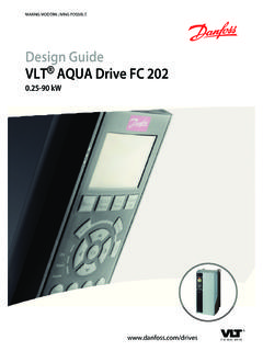
1 MAKING MODERN LIVING POSSIBLE. Output Filters Design Guide VLT AutomationDrive FC 300. VLT AQUA Drive FC 200. VLT hvac Drive FC 100. Contents Output Filters Design Guide Contents 1 How to Read this Design Guide 3. Abbreviations 3. 2 Safety and Conformity 4. Safety Precautions 4. CE Conformity and Labelling 4. 3 Introduction to Output Filters 5. Why use Output Filters 5. Protection of Motor Insulation 5. The Output Voltage 5. Reduction of Motor Acoustic Noise 7. Reduction of High Frequency Electromagnetic Noise in the Motor Cable 8. What are Bearing Currents and Shaft Voltages? 9. Mitigation of Premature Bearing Wear-Out 9. Measuring Electric Discharges in the Motor Bearings 10. Which Filter for which Purpose 12. dU/dt Filters 12. Sine-wave Filters 14. High-Frequency Common-Mode Core Kits 16. 4 Selection of Output Filters 17. How to Select the Correct Output Filter 17. product overview 17. HF-CM Selection 19. Electrical Data - dU/dt Filters 20.
2 Electrical Data - Sine-wave Filters 22. Spare Parts/Accessories 27. Cable Glands for Floor Standing Filters 27. Terminal Kits 28. Sine-Wave Filters 29. dU/dt Filters 30. Sine-Wave Foot Print Filter 31. 5 How to Install 32. Mechanical Mounting 32. Safety Requirements for Mechanical Installation 32. Mounting 32. Mechanical Installation of HF-CM 32. Earthing of Sine-wave and dU/dt Filters 33. - VLT is a registered Danfoss trademark 1. Contents Output Filters Design Guide Screening 33. Mechanical Dimensions 34. Sketches 34. 6 How to Programme the Frequency Converter 43. Parameter Settings for Operation with Sine-wave Filter 43. Index 44. 2 - VLT is a registered Danfoss trademark How to Read this Design Output Filters Design Guide 1 How to Read this Design Guide 1 1. This Design Guide will introduce all aspects of Output Filters Abbreviations for your frequency converter; from choosing the right Output filter for the application to instructions about how to install it Alternating current AC.
3 And how to program the frequency converter. American wire gauge AWG. Ampere/AMP A. Danfoss technical literature is also available online at Automatic Motor Adaptation AMA. Current limit ILIM. tations/Technical+Documentation. Degrees Celsius C. Direct current DC. Symbols Drive Dependent D-TYPE. Electro Magnetic Compatibility EMC. Symbols used in this manual Electronic Thermal Relay ETR. Drive FC. NOTE Gram g Indicates something to be noted by the reader. Hertz Hz Kilohertz kHz CAUTION Local Control Panel Meter LCP. m Indicates a general warning. Millihenry Inductance mH. Milliampere mA. WARNING Millisecond ms Indicates a high-voltage warning. Minute min Motion Control Tool MCT. Nanofarad nF. Indicates default setting Newton Meters Nm Nominal motor current IM,N. Nominal motor frequency fM,N. Nominal motor power PM,N. Nominal motor voltage UM,N. Parameter par. Protective Extra Low Voltage PELV. Rated Inverter Output Current IINV.
4 Revolutions Per Minute RPM. Second sec. Synchronous Motor Speed ns Torque limit TLIM. Volts V. IVLT,MAX The maximum Output current. IVLT,N The rated Output current supplied by the frequency converter. - VLT is a registered Danfoss trademark 3. Safety and Conformity Output Filters Design Guide 2 Safety and Conformity 2 2. NOTE. Safety Precautions Never attempt to repair a defect filter. Equipment containing electrical components may not be disposed of together with domestic NOTE. waste. The Filters presented in this Design Guide are specially It must be separately collected with electrical designed and tested for Danfoss frequency converters (FC. and electronic waste according to local and 102/202/301 and 302). Danfoss takes no resposibility for the currently valid legislation. use of third party Output Filters . MCC 101/102 NOTE. Design Guide The phased out LC- Filters that were developed for the VLT5000 series and are not compatible with the VLT FC.
5 100/200/300. However, the new Filters are compatible with both FC-series and VLT 5000-series NOTE. 690V applications: For motors not specially designed for frequency converter CE Conformity and Labelling operation or without double insulation, Danfoss highly recommend the use of either dU/dt or Sine-Wave Filters . What is CE Conformity and Labelling? The purpose of CE labelling is to avoid technical trade obstacles within EFTA and the EU. The EU has introduced the NOTE. CE label as a simple way of showing whether a product Sine-wave Filters can be used at switching frequencies higher complies with the relevant EU directives. The CE label says than the nominal switching frequency, but should never be nothing about the specifications or quality of the product . used at switching frequencies with less than 20% lower than The low-voltage directive (73/23/EEC) the nominal switching frequency. Frequency converters must be CE labelled in accordance with the low-voltage directive of January 1, 1997.
6 The NOTE. directive applies to all electrical equipment and appliances dU/dt Filters , unlike Sine-wave Filters , can be used at lower used in the 50 - 1000V AC and the 75 - 1500V DC voltage switching frequency than the nominal switching frequency, ranges. Danfoss CE-labels in accordance with the directive but higher switching frequency will cause overheating of the and issues a declaration of conformity upon request. filter and should be avoided. Warnings CAUTION. When in use the filter surface temperature rises. DO NOT. touch the filter during operation. WARNING. Never work on a filter in operation. Touching the electrical parts may be fatal - even after the equipment has been disconnected from the frequency converter or motor. WARNING. Before servicing the filter, wait at least the voltage discharge time stated in the Design Guide for the corresponding frequency converter to avoid electrical shock hazard. 4 - VLT is a registered Danfoss trademark Introduction to Output Output Filters Design Guide 3 Introduction to Output Filters Why use Output Filters This chapter describes why and when to use Output Filters with Danfoss frequency converters.
7 It is divided into 4. the motor cable (type, cross-section, length, screened or unscreened, inductance and 3 3. sections: capacitance). the high frequency surge impendance of the motor Protection of Motor Insulation Because of the impedance mismatch between the cable Reduction of Motor Acoustic Noise characteristic impedance and the motor surge impedance a Reduction of High Frequency Electromagnetic wave reflection occurs, causing a ringing voltage overshoot Noise in Motor Cable at the motor terminals - see Illustration The motor surge impedance decreases with the increase of motor size Bearing currents and shaft voltage resulting in reduced mismatch with the cable impedance. The lower reflection coefficient ( ) reduces the wave Protection of Motor Insulation reflection and thereby the voltage overshoot. Typical values are given in Table The Output Voltage In the case of parallel cables the cable characteristic impedance is reduced, resulting in a higher reflection The Output voltage of the frequency converter is a series of coefficient higher overshoot.
8 For more information please trapezoidal pulses with a variable width (pulse width see IEC 61800-8. modulation) characterized by a pulse rise-time tr. When a transistor in the inverter switches, the voltage across the motor terminal increases by a dU/dt ratio that depends on: Illustration Example of Converter Output Voltage (dotted line) and Motor Terminal Voltage After 200m of Cable (solid line). - VLT is a registered Danfoss trademark 5. Introduction to Output Output Filters Design Guide Typical values for the rise time and peak voltage UPEAK are The IEC and NEMA Definitions of Risetime tr measured on the motor terminals between two phases. Two different definitions for the risetime tr are used in practice. The international IEC standards define the rise-time 3 3. as the time between 10% to 90% of the peak voltage Upeak. The US National Electrical Manufacturers Association (NEMA). defines the rise-time as the time between 10% and 90% of the final, settled voltage, that is equal to the DC link voltage UDC.
9 See Illustration and Illustration Illustration IEC. To obtain approximate values for cable lengths and voltages not mentioned below, use the following rules of thumb: 1. Rise time increases with cable length. 2. UPEAK = DC link voltage x (1+ ); represents the reflection coefficient and typical values can be found in table below (DC link voltage = Mains voltage x ). 3. U PEAK. dU/dt = tr (IEC). U DC Illustration NEMA. dU/dt = tr ( NEMA ). (NEMA). (For dU/dt, rise time, Upeak values at different cable lengths please consult the drive Design Guide ) Various standards and technical specifications present limits of the admissible Upeak and tr for different motor types. Some of the most used limit lines are shown in Illustration Motor power [kW] Zm [ ] . < 2000 - 5000 90 800 IEC 60034-17 limit line for general purpose motors when fed by frequency converters, 500V. 355 400 motors. Table Typical Values for Reflection Coefficients (IEC 61800-8).
10 IEC 60034-25 limit for converter rated motors: curve A is for 500V motors and curve B is for 690V. motors. NEMA MG1 Definite purpose Inverter Fed Motors. If, in your application, the resulting Upeak and tr exceed the limits that apply for the motor used, an Output filter should be used for protecting the motor insulation. 6 - VLT is a registered Danfoss trademark Introduction to Output Output Filters Design Guide 3 3. Illustration Limit Lines for Upeak and Risetime tr. Reduction of Motor Acoustic Noise The acoustic noise generated by motors has three main sources. 1. The magnetic noise produced by the motor core, through magnetostriction 2. The noise produced by the motor bearings 3. The noise produced by the motor ventilation When a motor is fed by a frequency converter, the pulsewidth modulated (PWM) voltage applied to the motor causes additional magnetic noise at the switching frequency and harmonics of the switching frequency (mainly the double of the switching frequency).