Transcription of Part 2: Using FMEA, DFR, Test and Failure Analysis …
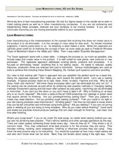
1 Part 2: Using FMEA, DFR, Test andFailure Analysis in lean NPDO verview Introduction and Definitions Part 1: lean Product Development lean vs. Traditional Product Development Key Elements of lean NPD Customer Defines Value Front Loaded and Knowledge Based Eliminate Redesign Waste Reliability Requirements Part 2: Reliability Elements of lean NPD lean FMEA and DRBFM Critical Characteristics DFR and Physics of Failure Accelerated Testing to Failure Failure Analysis and Knowledge CaptureLean FMEA Some teams attempt to lean FMEA process by creating product family FMEA sbut fail to update FMEA for newapplications or changes Instead lean FMEA Should Focus on NewDesign Features and Changes to BaselineDesign to Assess Associated RisksTools to Focus lean FMEA Diagramming Tools Functional Block Diagram Boundary Diagram Parameter Diagram Process Flow Diagram Highlight Changes to Product
2 Or Processon the DiagramsFunctional Block DiagramAnnotate Retained and Changed Items & FunctionsBoundary Diagram ConstructionSubsystem 1 Subsystem 3 Subsystem 2 FMEA BoundaryInterface-Physical Interface-Info Transfer-Data Transfer-External InputConsider a Functional Block Diagram of the SystemWith Modules and InterfacesParameter Diagram ofProduct, Process, SystemProduct, Process,or SystemNoiseFactorsResponse(Output, Function)Control FactorsSignal(Inputs)Elements of the P-Diagram Controlled by Input Function Static or Dynamic May be Variable Performance Mean, Std Dev Customer Requirement Forces Beyond Control Cause Output Variation Environment Factors Functional Design Parameters Fixed or Adjustable Fundamental to Design of Function Reduce VariationProcess Flow DiagramAnnotate Retained and Changed Process StepsSelecting Process Steps for Analysis On Process Flow Map.
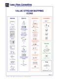
3 Identify Steps Being Modified Identify New Steps Required for New Product Drill Down to Identify Sub-Steps Within theTarget Steps Identified for Analysis Complete lean PFMEA on SelectedProcess Steps Integrate with Previous PFMEA onStandard / Unchanged Process StepsKey Characteristics Include: Product Features Manufacturing Processes Assembly Characteristics That Significantly Affect: Product Performance Form, Fit, Function lean NPD Focuses on the Critical FewCharacteristics the Customer ValuesKey CharacteristicsDetectPreventRPNDETOCCSEV A ctionTakenAction ResultsResponse &TargetCompleteDateRecommendedActionsRPN D etecCurrentControlsOccurPotentialCause(s )/Mechanism(s)Of FailureClassSevPotentialEffect(s) ofFailurePotentialFailureModeItem /ProcessStepDetectPreventRPNDETOCCSEVA ctionTakenAction ResultsResponse &TargetCompleteDateRecommendedActionsRPN D etecCurrentDesignControlsOccurPotentialC ause(s)/Mechanism(s)Of FailureClassSevPotentialEffect(s)
4 OfFailurePotentialFailureModeItem /ProcessStepFunctionDFMEA &PFMEAT echnical Requirements,Tools Identify SpecialProduct CharacteristicsSeverityProcess StepsReceive MaterialMaterial handlingShipping DamageComponent ManufactureVehicle AssemblyPrimary Drive Manufacturing Process StepsOp 100 Step 1 PRE-LOAD DOW EL PINS TOFIXTUREOp 100 Step 2 PRE-LOAD JACK SHAFTSEAL TO FIXTUREOp 100 Step 3 PRE-LOAD PRIMARYHOUSING BUSHING TOFIXTUREOp 110 Pre-load bearing to fixture #2Op 120 Pre-load main shaft oil seal tomandrelOp 200 Housing to fixture #1Op 210 Operate pressOp 220 Retaining ring to top grooveOp 230 Reload fixture #1Op 300 Housing to
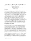
5 Fixture #2Op 310 Operate pressOp 320 Retaining ring to top grooveOp 330 Mandrel to main shaft bore 340 Operate pressOp 350Re-load fixture #2 and mandrelOp 400 Housing to tableOp 410 ReservedOp 420 Chain adj sub assy to housingOp 430 Lubricate bushing & sealOp 445 Move or stage for final assyOp 10O-ring to shifter tubeOp 500 Shifter tube to housingOp 510 Clamp to shifter tubeOp 20 Assemble shifter leverOp 520W ave washer to shifter leverOp 530 Shifter lever to shifter tubeOp 535 Que for final assy lineCustomerAssessmentDirection of ImprovementPotential Critical and TO " FACE OF PRIMARY HOUSINGBUSHING TO FACE OF JACK SHAFTSEALDOW EL PINS TO " TOFACEJACK SHAFT SEAL AGAINSTSHOULDERBEARING FLUSH TO SNAP RING FACESEAL COMPRESSION HEIGHTPRIMARY GASKET SEAL SURFACE FINISHSERATION DAMAGEW eighted ImportanceRelative ImportanceGFHFHFGFGHGHHFHHFFYHHHHHGGF539 3995081817209410027542613054813000270459 90000000 Special CharacteristicsMatrixCharacteristics MatrixRequirements Documents Customer Specification Regulatory Dimensions AppearanceRequirements DocumentDrawingsField HistoryRobustness Tools
6 Functional Block Diagram Boundary Diagram P-Diagram Interface MatrixIdentifying Key Characteristics1098765432112345678910 OccurrenceSeverityPotential Critical CharacteristicPotential Key CharacteristicPossible Annoyance ZoneSpecial Characteristics MatrixSeverityProcess StepsReceive MaterialMaterial handlingShipping DamageComponent ManufactureVehicle AssemblyPrimary Drive Manufacturing Process StepsOp 100 Step 1 PRE-LOAD DOW EL PINS TOFIXTUREOp 100 Step 2 PRE-LOAD JACK SHAFTSEAL TO FIXTUREOp 100 Step 3 PRE-LOAD PRIMARYHOUSING BUSHING TOFIXTUREOp 110 Pre-load bearing to fixture #2Op 120 Pre-load main shaft oil seal tomandrelOp 200 Housing to fixture #1Op 210 Operate pressOp 220 Retaining ring to top grooveOp 230 Reload fixture #1Op 300 Housing to fixture #2Op 310 Operate pressOp 320 Retaining ring to top grooveOp 330 Mandrel to main shaft bore 340 Operate pressOp 350Re-load fixture #2 and mandrelOp 400 Housing to tableOp 410 ReservedOp 420 Chain adj sub assy to housingOp 430 Lubricate bushing & sealOp 445 Move or stage for final assyOp 10O-ring to shifter tubeOp 500 Shifter tube
7 To housingOp 510 Clamp to shifter tubeOp 20 Assemble shifter leverOp 520W ave washer to shifter leverOp 530 Shifter lever to shifter tubeOp 535 Que for final assy lineCustomerAssessmentDirection of ImprovementPotential Critical and TO " FACE OF PRIMARY HOUSINGBUSHING TO FACE OF JACK SHAFTSEALDOW EL PINS TO " TOFACEJACK SHAFT SEAL AGAINSTSHOULDERBEARING FLUSH TO SNAP RING FACESEAL COMPRESSION HEIGHTPRIMARY GASKET SEAL SURFACE FINISHSERATION DAMAGEW eighted ImportanceRelative ImportanceLHMHMHLHHMLMMHMMHHMMMMMMLLH539 3995081817209410027542613054813000270459 90000000 Special CharacteristicsMatrixProcess Steps from Flow ChartCharacteristics from Requirements and DFMEAE ffect of Step onCharacteristicsDeveloping the Control Plan Prioritize Process Risks Identified in thePFMEA and the Special CharacteristicsMatrix Process Flow Diagram Lessons Learned from Similar Processes Process Control Data from RelatedProcesses Measurements Required for Process Control SPC Control Limits Complete the Items in Control Plan TemplateControl Plan ItemsMachine.
8 Device, Jig,Tools for each operation that is described,identify the processing equipment machine, device,jig, or other toolsfor manufacturing, as across reference numberfrom all applicable documents such as, but not limited to,process flow diagram, numbered blue print, FMEAs, and or properties of a part, component or assemblythat are described on drawingsor other primary engineering info. Compilation of important product variables that have a cause and effect relationship with the identified those process characteristics for which variation must becontrolled to minimize product variation.
9 There may be more than one processcharacteristic for each product be obtained from various engineering documents, such as, butnot limited to, drawings, design reviews, material standard, computer aided design data,manufacturing, and/or assembly the measurement systembeing used, including, gages, fixtures, tools, and/or testequipment required to measure the part/process/manufacturing sampling is required list thecorresponding size and MethodBrief description ofhow the operation will be controlled, including procedure numberswhere may be controlled by SPC, inspection, attribute data,mistake proofing, sampling plans, and other.
10 If elaborate control procedures are used,reference document by ID PlanSpecify the corrective actions necessary to avoid producing nonconforming productsor operating out of control. May also refer to a specific reaction plan number and identifythe person responsible for the the Control Plan For Critical Characteristics, Use ControlPlan to Identify: Measurements: How, When, How Often Controls to Keep Characteristic in Tolerance Actions if Characteristic Out of Tolerance Containment Corrective Actions Robust Design + Controlled Processes =Reliable ProductsDRBFM and DRBTRD esign Review Based on Failure Modes & Test ResultsK