Transcription of Peripheral Devices - PVPSIT
1 1 UNIT-V UNIT-V INPUT-OUTPUT ORGANIZATION Peripheral Devices : The Input / output organization of computer depends upon the size of computer and the peripherals connected to it. The I/O Subsystem of the computer, provides an efficient mode of communication between the central system and the outside environment The most common input output Devices are: i) Monitor ii) Keyboard iii) Mouse iv) Printer v) Magnetic tapes The Devices that are under the direct control of the computer are said to be connected online. Input - Output Interface Input Output Interface provides a method for transferring information between internal storage and external I/O Devices . Peripherals connected to a computer need special communication links for interfacing them with the central processing unit.
2 The purpose of communication link is to resolve the differences that exist between the central computer and each Peripheral . The Major Differences are:- 1. Peripherals are electromechnical and electromagnetic Devices and CPU and memory are electronic Devices . Therefore, a conversion of signal values may be needed. 2. The data transfer rate of peripherals is usually slower than the transfer rate of CPU and consequently, a synchronization mechanism may be needed. 3. Data codes and formats in the peripherals differ from the word format in the CPU and memory. 2 UNIT-V 4. The operating modes of peripherals are different from each other and must be controlled so as not to disturb the operation of other peripherals connected to the CPU. To Resolve these differences, computer systems include special hardware components between the CPU and Peripherals to supervises and synchronizes all input and out transfers These components are called Interface Units because they interface between the processor bus and the Peripheral Devices .
3 I/O BUS and Interface Module It defines the typical link between the processor and several peripherals. The I/O Bus consists of data lines, address lines and control lines. The I/O bus from the processor is attached to all peripherals interface. To communicate with a particular device, the processor places a device address on address lines. Each Interface decodes the address and control received from the I/O bus, interprets them for peripherals and provides signals for the Peripheral controller. It is also synchronizes the data flow and supervises the transfer between Peripheral and processor. Each Peripheral has its own controller. For example, the printer controller controls the paper motion, the print timing The control lines are referred as I/O command.
4 The commands are as following: Control command- A control command is issued to activate the Peripheral and to inform it what to do. Status command- A status command is used to test various status conditions in the interface and the Peripheral . Data Output command- A data output command causes the interface to respond by transferring data from the bus into one of its registers. Data Input command- The data input command is the opposite of the data output. In this case the interface receives on item of data from the Peripheral and places it in its buffer register. I/O Versus Memory Bus 3 UNIT-V To communicate with I/O, the processor must communicate with the memory unit. Like the I/O bus, the memory bus contains data, address and read/write control lines.
5 There are 3 ways that computer buses can be used to communicate with memory and I/O: i. Use two Separate buses , one for memory and other for I/O. ii. Use one common bus for both memory and I/O but separate control lines for each. iii. Use one common bus for memory and I/O with common control lines. I/O Processor In the first method, the computer has independent sets of data, address and control buses one for accessing memory and other for I/O. This is done in computers that provides a separate I/O processor (IOP). The purpose of IOP is to provide an independent pathway for the transfer of information between external device and internal memory. Asynchronous Data Transfer : This Scheme is used when speed of I/O Devices do not match with microprocessor, and timing characteristics of I/O Devices is not predictable.
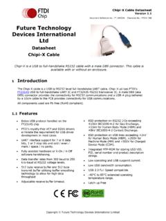
6 In this method, process initiates the device and check its status. As a result, CPU has to wait till I/O device is ready to transfer data. When device is ready CPU issues instruction for I/O transfer. In this method two types of techniques are used based on signals before data transfer. i. Strobe Control ii. Handshaking 4 UNIT-V Strobe Signal : The strobe control method of Asynchronous data transfer employs a single control line to time each transfer. The strobe may be activated by either the source or the destination unit. Data Transfer Initiated by Source Unit: In the block diagram fig. (a), the data bus carries the binary information from source to destination unit. Typically, the bus has multiple lines to transfer an entire byte or word.
7 The strobe is a single line that informs the destination unit when a valid data word is available. The timing diagram fig. (b) the source unit first places the data on the data bus. The information on the data bus and strobe signal remain in the active state to allow the destination unit to receive the data. Data Transfer Initiated by Destination Unit: In this method, the destination unit activates the strobe pulse, to informing the source to provide the data. The source will respond by placing the requested binary information on the data bus. The data must be valid and remain in the bus long enough for the destination unit to accept it. When accepted the destination unit then disables the strobe and the source unit removes the data from the bus.
8 5 UNIT-V Disadvantage of Strobe Signal : The disadvantage of the strobe method is that, the source unit initiates the transfer has no way of knowing whether the destination unit has actually received the data item that was places in the bus. Similarly, a destination unit that initiates the transfer has no way of knowing whether the source unit has actually placed the data on bus. The Handshaking method solves this problem. Handshaking: The handshaking method solves the problem of strobe method by introducing a second control signal that provides a reply to the unit that initiates the transfer. Principle of Handshaking: The basic principle of the two-wire handshaking method of data transfer is as follow: One control line is in the same direction as the data flows in the bus from the source to destination.
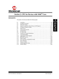
9 It is used by source unit to inform the destination unit whether there a valid data in the bus. The other control line is in the other direction from the destination to the source. It is used by the destination unit to inform the source whether it can accept the data. The sequence of control during the transfer depends on the unit that initiates the transfer. Source Initiated Transfer using Handshaking: The sequence of events shows four possible states that the system can be at any given time. The source unit initiates the transfer by placing the data on the bus and enabling its data valid signal. The data accepted signal is activated by the destination unit after it accepts the data from the bus. The source unit then disables its data accepted signal and the system goes into its initial state.
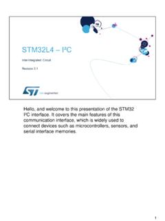
10 6 UNIT-V Destination Initiated Transfer Using Handshaking: The name of the signal generated by the destination unit has been changed to ready for data to reflects its new meaning. The source unit in this case does not place data on the bus until after it receives the ready for data signal from the destination unit. From there on, the handshaking procedure follows the same pattern as in the source initiated case. The only difference between the Source Initiated and the Destination Initiated transfer is in their choice of Initial sate. 7 UNIT-V Advantage of the Handshaking method: The Handshaking scheme provides degree of flexibility and reliability because the successful completion of data transfer relies on active participation by both units.