Transcription of Phase Control Using Thyristors - Learn About Electronics
1 401 Revised: 09/23/13 2013 Littelfuse, IncSpecifications are subject to change without notice. Teccor brand ThyristorsAN1003 Phase Control Using ThyristorsIntroductionDue to high-volume production techniques, Thyristors are now priced so that almost any electrical product can benefit from electronic Control . A look at the fundamentals of SCR and Triac Phase controls shows how this is power CharacteristicsPhase Control is the most common form of thyristor power Control . The thyristor is held in the off condition -- that is, all current flow in the circuit is blocked by the thyristor except a minute leakage current.
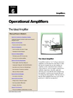
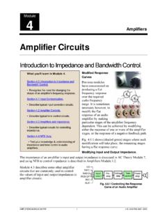
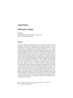
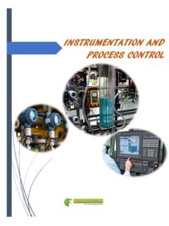
2 Then the thyristor is triggered into an on condition by the Control full-wave AC Control , a single Triac or two SCRs connected in inverse parallel may be used. One of two methods may be used for full-wave DC Control -- a bridge rectifier formed by two SCRs or an SCR placed in series with a diode bridge as shown in Figure SCR AC ControlControlCircuitTriac AC ControlLineLoadControlCircuitOne SCR DC ControlControlCircuitLineLineLoadTwo SCR DC ControlLoadFigure SCR/Triac Connections for Various Methods of Phase ControlFigure illustrates voltage waveform and shows common terms used to describe thyristor operation.
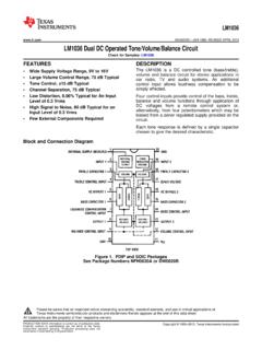
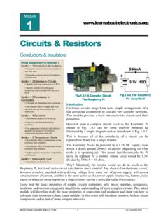
3 Delay angle is the time during which the thyristor blocks the line voltage. The conduction angle is the time during which the thyristor is Control Using ThyristorsIt is important to note that the circuit current is determined by the load and power source. For simplification, assume the load is resistive; that is, both the voltage and current waveforms are Rectified OperationVoltage Applied to LoadDelay (Triggering) AngleConduction AngleFigure Sine Wave Showing Principles of Phase ControlDifferent loads respond to different characteristics of the AC waveform.
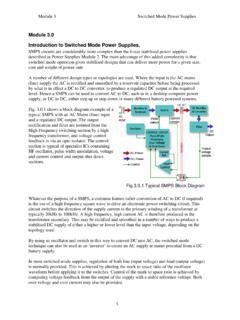
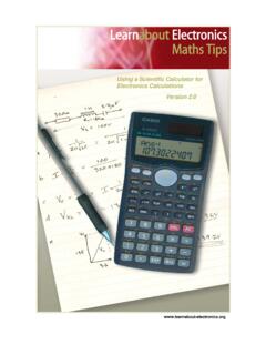
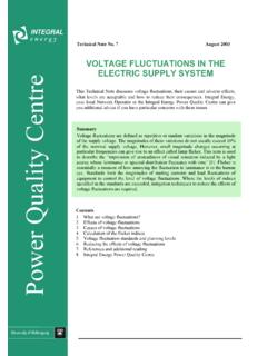
4 For example, some are sensitive to average voltage, some to RMS voltage, and others to peak voltage. Various voltage characteristics are plotted against conduction angle for half- and full-wave Phase Control circuits in Figure and Figure 20 40 60 80 100 120 140 Conduction Angle ( )Normalized Sine Wave RMS Voltage Poweras Fraction of Full ConductionHALF WAVE 180160 Figure Half-Wave Phase Control (Sinusoidal)402 Revised: 09/23/13 2013 Littelfuse, IncSpecifications are subject to change without notice. Teccor brand ThyristorsAN1003 Phase Control Using ThyristorsPeak 20 40 60 80 100 120 140 Conduction Angle ( )Normal Sine Wave RMS Voltage Poweras Fraction of Full ConductionFULL WAVEP owerAVG 180160 Figure Symmetrical Full-Wave Phase Control (Sinusoidal)Figure and Figure also show the relative power curve for constant impedance loads such as heaters.
5 Because the relative impedance of incandescent lamps and motors change with applied voltage, they do not follow this curve precisely. To use the curves, find the full-wave rated power of the load, and then multiply by the ratio associated with the specific Phase angle. Thus, a 180 conduction angle in a half-wave circuit provides x full-wave conduction a full-wave circuit, a conduction angle of 150 provides 97% full power while a conduction angle of 30 provides only 3% of full power Control . Therefore, it is usually pointless to obtain conduction angles less than 30 or greater than 150.
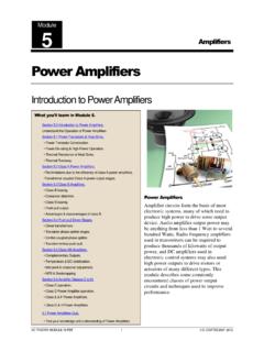
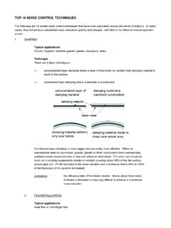
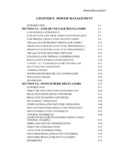
6 Figure and Figure give convenient direct output voltage readings for 115 V/230 V input voltage. These curves also apply to current in a resistive Voltage1801601401201008060402000 20 40 60 80 100 120 140 Conduction Angle ( )RMSAVGO utput Voltage36032028024020016012080400 InputVoltage230 V115 VHALF WAVE 180160 Figure Output Voltage of Half-wave PhasePeak VoltageRMS0 20 40 60 80 100 120 140 Conduction Angle ( )AVGO utput Voltage36032028024020016012080400 InputVoltage230 V115 V180160140120100806040200 FULL WAVE 180160 Figure Output Voltage of Full-wave Phase Control403 Revised.
7 09/23/13 2013 Littelfuse, IncSpecifications are subject to change without notice. Teccor brand ThyristorsAN1003 Phase Control Using ThyristorsA relaxation oscillator is the simplest and most common Control circuit for Phase Control . Figure illustrates this circuit as it would be used with a thyristor . Turn-on of the thyristor occurs when the capacitor is charged through the resistor from a voltage or current source until the breakover voltage of the switching device is reached. Then, the switching device changes to its on state, and the capacitor is discharged through the thyristor gate.
8 Trigger devices used are neon bulbs, unijunction transistors, and three-, four-, or five-layer semiconductor trigger devices. Phase Control of the output waveform is obtained by varying the RC time constant of the charging circuit so the trigger device breakdown occurs at different Phase angles within the controlled half or full Relaxation Oscillator thyristor Trigger CircuitFigure shows the capacitor voltage-time characteristic if the relaxation oscillator is to be operated from a pure DC ConstantsRatio of (Capacitor VoltageSupply Source Voltage)
9 Figure Capacitor Charging from DC SourceUsually, the design starting point is the selection of a capacitance value which will reliably trigger the thyristor when the capacitance is discharged. Trigger devices and thyristor gate triggering characteristics play a part in the selection. All the device characteristics are not always completely specified in applications, so experimental determination is sometimes final selection of the capacitor, the curve shown in Figure can be used in determining the charging resistance needed to obtain the desired Control circuits begin each half-cycle with the capacitor voltage at or near zero.
10 However, most circuits leave a relatively large residual voltage on the capacitor after discharge. Therefore, the charging resistor must be determined on the basis of additional charge necessary to raise the capacitor to trigger example, assume that we want to trigger an S2010L SCR with a 32 V trigger DIAC. A F capacitor will supply the necessary SCR gate current with the trigger DIAC. Assume a 50 V dc power supply, 30 minimum conduction angle, and 150 maximum conduction angle with a 60 Hz input power source.