Transcription of Phase sensitive detection: the lock-in amplifier
1 Phase sensitive detection: the lock-in amplifier by Dr. G. Bradley Armen Department of Physics and Astronomy 401 Nielsen Physics Building The University of Tennessee Knoxville, Tennessee 37996-1200. Copyright April 2008 by George Bradley Armen*. *All rights are reserved. No part of this publication may be reproduced or transmitted in any form or by any means, electronic or mechanical, including photocopy, recording, or any information storage or retrieval system, without permission in writing from the author.
2 A. introduction Phase - sensitive detection is a powerful method for seeing very small signals in the presence of overwhelming noise. Developed in the 1960's, it's become a ubiquitous experimental technique, and the lock-in amplifier1 is the instrument which makes this method possible. In this laboratory we'll learn about the method in some generality, and apply it to measure some very small quantities which would be impossible by conventional means. The laboratory consists (like life) of three stages: First we'll look at a synthetic signal in the presence of some well behaved noise'.
3 This will give us some insight into the lock- in's behavior in the real world. Next, we'll perform the classic light-bulb experiment'. which gives a lasting impression of the power of the technique. We'll actually be able to measure the intensity of a flash-light bulb placed at the far end of the 3rd floor hallway, in the presence of all the lighting from the overhead and Coke machines with a very poor detector2. Finally, we'll apply the method to the more serious problem of measuring the 1. If Wikipedia is to be believed: The lock-in amplifier was invented by physicist Robert Dicke of Princeton University, who founded the company Princeton Applied Research (PAR) to market the product.
4 2. Our eyes can do it, but they're very, very good detectors! 1. Faraday effect. Here, polarized light passing through a dielectric material in the presence of a weak magnetic field rotates slightly. This angle of polarization rotation is very small ( ) but we'll be able to measure this easily and accurately. The actual purpose of this lab is to leave you with some working knowledge of lock-in amplifiers and what they're good for. At some point in your future career you may very well be designing experiments of your own, and a vague memory of this lab and Phase - sensitive capabilities may put you on a fruitful track.
5 B. Phase sensitive detection A lock-in , or Phase - sensitive , amplifier is simply a fancy AC voltmeter. Along with the input, one supplies it with a periodic reference signal. The amplifier then responds only to the portion of the input signal that occurs at the reference frequency with a fixed Phase relationship. By designing experiments that exploit this feature, it's possible to measure quantities that would otherwise be overwhelmed by noise. The lock-in amplifier operates on a very simple scheme: Consider a sinusoidal input signal V (t ) = V0 sin( t + ).
6 Suppose we also have available a reference signal VR (t ) = sin( t ) . The product of these two gives beats at the sum and difference frequencies V (t )VR (t ) =. V0. { cos[( )t + ] cos[( + )t + ] }. 2. 2. When the input signal has a frequency different from the reference frequency , the product oscillates in time with an average value of zero. However, if = we get a sinusoidal output, offset by a DC (zero frequency) level: V (t )VR (t ) =. V0. { cos[ ] cos[2 t + ] } = . 2. If we can extract the DC component of this product, and are able to adjust , we get a direct measure of the signal amplitude V0.
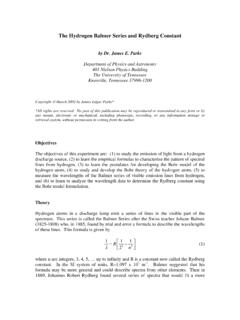
7 So, we arrange to have our quantity of interest oscillate at ; any unwanted signals oscillating at different frequencies are rejected. Furthermore, any random3 noise that does oscillate at will also be rejected. The following figure illustrates how a lock-in works: Fig. 1 Block diagram of Phase - sensitive detection. The input signal V(t) passes through a capacitor, blocking any pre-existing DC offset, and is then amplified4 (A). The reference signal VR(t) passes through an adjustable Phase - shifter ( ). These two results are then multiplied, and any resulting DC component is extracted by the low-pass ( ) filter.
8 3. By random, we mean that the noise signal has a time-dependant Phase , and upon averaging gives zero. 4. The amplifier may be in stages, before or after the multiplier, or both. 3. The idea is simple enough, but the actual implementation is difficult and Lock-ins tend to be expensive. While this isn't an electronics class, a few of the details are worth noting: First, the actual reference signal need not be sinusoidal. Lock-ins take the reference signal, pass it through a Phase shifter, and then create their own internal reference locked' to the Phase -shifted external reference.
9 This allows for much greater flexibility (and reliability) in operation. Also, the input need not be sinusoidal, merely periodic with frequency . The lock-in then picks out the fundamental Fourier component of the input waveform. Second, the low-pass filter is not perfect. In fact, if it were perfect, the instrument would be largely useless. We'll look at this in more detail presently. Finally, the multiplier (or demodulator') is a tricky device to implement in analog form (or used to be). If one first digitizes the input and reference, then of course multiplication is simple.
10 However, there are some disadvantages inherent to the digital approach, primarily one of dynamic range if you digitize the input with a certain precision (bits) the ability of the instrument to extract small signals is of course limited. Thus, when shopping today one can find both digital and analog models, each having their own merits. Older models (like the one you'll be using, naturally) are analog, but additionally don't realize the exact scheme outlined above: Because the multiplication circuitry is difficult, in older lock-ins the polarity of the input signal is reversed periodically at the reference frequency.


![arXiv:2203.06454v1 [physics.plasm-ph] 12 Mar 2022](/cache/preview/9/2/6/d/f/a/8/1/thumb-926dfa81e51e569016b61e30d7be9ca5.jpg)