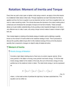
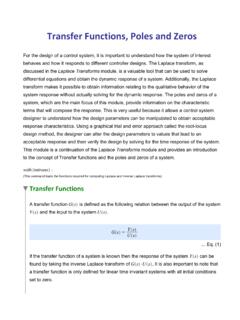
Transcription of PID Control - Waterloo Maple
1 PID ControlProportional-Integral-Derivative (PID) controllers are one of the most commonly used types of controllers. They have numerous applications relating to temperature Control , speed Control , position Control , etc. A PID controller provides a Control signal that has a component proportional to the tracking error of a system, a component proportional to the accumulation of this error over time and a component proportional to the time rate of change of this error. This module will cover these different components and some of their different combinations that canbe used for Control purposes. Fig. 1: System block diagram with feedback Control (This command loads the functions required for computing Laplace and Inverse Laplace transforms. For more information on Laplace transforms, see the Laplace Transforms and Transfer Functions module.) proportional Control (P)A proportional controller outputs a Control signal that is proportional to the error signal.
2 Eq. (1)where is the proportional gain. In the Laplace domain, this can be written Eq. (2)First order systems with P controlThe characteristic form of the transfer function of a first order plant Eq. (3)where is the time constant and is the DC Gain. With P Control , the closed loop transfer function of the system Eq. (4)(This can be obtained using where is the controller transferfunction and is the plant transfer function. See the Block Diagrams, Feedback and Transient Response Specifications module for more information.) This transfer function is still a first order transfer function and can be written Eq. (5) Comparing Eq. (5) with Eq. (3), the closed loop time constant Eq. (6)This shows that proportional Control can be used to alter the rise time and settling time ofa first order system. Using Eq. (5) with a step input of magnitude , the steady-state error for a first order system with proportional Control Eq.
3 (7)This shows that the steady state error can be reduced by increasing the gain. However, to achieve zero steady-state error, the gain would have to approach infinity. Therefore, for a first order system, a proportional controller cannot be used to eliminate the step response steady state error. The following plot shows the response of a system with a plant transfer function to a unit-step input. Rise timeSettling timeSteady-state errorsecsecSecond order systems with P controlThe characteristic form of the transfer function of a second order plant Eq. (8)where is the damping ratio and is the natural frequency. With P Control , the closed loop transfer function of the system Eq. (9)Comparing Eq. (9) with Eq. (8), the closed loop natural frequency and damping ratio Eq. (10) Eq. (11) This shows that as is increased, the natural frequency increases and the damping ratio decreases which results in larger and faster oscillations.
4 Since the rise, settling and peak times all depend on both of these parameters it is possible to alter them by adjusting . The same applies for the maximum overshoot which depends on the damping ratio. With a step input of magnitude , the steady-state error for the closed loop transfer function Eq. (12)This shows that the steady state error can be reduced by increasing the gain. However, similar to the proportional Control of a first order system, zero steady-state error would require the proportional gain to approach infinity. Therefore, for a second order system, aproportional controller cannot be used to eliminate the step response steady state error. The following plot shows the system response of a system with a plant transfer function to a unit-step input . Damping ratioNatural frequencyDamped frequencyrad/srad/sRise timeMaximum OvershootSteady-state errorsec%As can be seen, since all these parameters depend on , the Control on the system response specifications is limited.
5 For example, this type of a controller does not allow both the steady-state error and the maximum overshoot to be reduced at the same time. Integral Control (I)An integral controller outputs a Control signal that is proportional to the integral of the error signal :.. Eq. (13)where is the integral gain. In the Laplace domain, this can be written Eq. (14)The integral component of a contoller provides a signal based on how long an error works to prevent this persistance of an error by increasing the Control signal with time. This helps reduces the steady state error and in some cases, depending on the type of system and the type of reference signal, eliminates it. I Control is usually not used on its own, however it is more effective than P Control for eliminating the step response steady-state error of a first order plant. For a second order plant, using I Control leads to a third order system that, depending on the system parameters, can result in unstable oscillations.
6 First order systems with I controlWith I Control , the closed loop transfer function of a first order system Eq. (15)This can be written Eq. (16)Therefore, the equivalent natural frequency and damping ratio Eq. (17) Eq. (18)Also, with a step input of magnitude , the steady-state error Eq. (19)This shows that integral Control can be used to eliminate steady state error for a step input and have Control over the response characteristics. Once again, similar to the case of P Control for a second order system, since all the response specifications depend on the controller gain , it is not possible to Control them independently. For example, it is not possible to reduce the rise time and maximum overshoot simultaneously. The following plot shows a comparison of the unit-step responses of a first order system with proportional Control and with integral Control (plant transfer function: ).
7 Derivative Control (D)A derivative controller outputs a Control signal that is proportional to the time derivativeof the error signal :.. Eq. (20)where is the derivative gain. In the Laplace domain, this can be written as .. Eq. (21)The derivative component of a controller helps reduce overshoot. It is used to reduce the rate of change of the tracking error in order to prevent overshoot due to the inertia of the system. Derivative Control is not covered in more detail by itself because it does not track error, only the rate of change of it. proportional Integral Control (PI)PI Control is a combination of proportional and integral Control :.. Eq. (22)In the Laplace domain this can be written Eq. (23)First order systems with PI controlWith PI Control , the closed loop transfer function of a first order system Eq. (24)This results in a second order system that can be written Eq. (25)so the equivalent natural frequency and damping ratio Eq.
8 (26) Eq. (27)The steady state error for a step input of magnitude Eq. (28)This shows that proportional -integral Control eliminates the step response steady state error and allows for more Control over the transient response (compared to only P or onlyI Control ) because both the damping ratio and natural frequency can be altered using the gains. For example, it is now possible to reduce the rise time and maximum overshoot simultaneously. The following plot shows a comparison of the unit-step responses of a first order system with proportional Control , integral Control and proportional -integral Control (plant transfer function: ). Second order system with PI controlWith PI Control , the closed loop transfer function of a second order system Eq. (29)This is now a third order system with a zero. For a step input of magnitude , the steady state error is .. Eq. (30)This is an improvement over the other types of controllers discussed so far.
9 Since the transfer function is a third order system and has a pole, it requires other methods like dominant pole analysis and root locus methods to analyze. It can also be tuned using approximate trial and error approaches to achieve the desired characteristics (use slidersbelow).The following plot shows a comparison of the unit-step responses of a second order system with proportional Control and proportional -integral Control (plant transfer function: ). As can be observed, the Control over the response is still Derivative Control (PD)PD Control is a combination of proportional and derivative Control :.. Eq. (31)In the Laplace domain this can be written Eq. (32)First order systems with PD controlWith PD Control , the closed loop transfer function of a first order system Eq. (33)This results in a modified first order system with a zero that can be written Eq. (34)In this case, the steady state error for a step input remains the same as the steady state error with pure proportional Control .
10 There is no significant value added by including the derivative order systems with PD controlWith PD Control , the closed loop transfer function of the system Eq. (35)This is now a second order system with a zero. The step response steady state error is the same as with proportional Control :.. Eq. (36)For the design of such a system, the transfer function can be reduced to a second order system by ignoring the effect of the zero and calculating estimates for the required gains to meet the desired specifications. Then the response can be plotted and the gains can be tuned using a trial and error approach until the specifications are met. As can be seenfrom the transfer function, PD Control allows for both the damping ratio and natural frequency to be controlled separately. For the approximate second order system, the natural frequency and damping ratio Eq. (37) Eq. (38)The following plot shows a comparison of the unit-step responses of a second order system with P Control and PD Control (plant transfer function: ).