Transcription of PIPE FREEZE PROTECTION AND FLOW …
1 This step-by-step design guide provides the tools necessary to design a Raychem XL-Trace pipe FREEZE PROTECTION or flow maintenance system. For other applications or for design assistance, contact your Thermal Management representative or call (800) 545-6258. Also, visit our web site at ..1 How to Use this Guide ..2 Safety Guidelines ..2 Warranty ..3 System Overview ..3XL-Trace Applications ..3 self - regulating heating cable Construction ..4 Pipe FREEZE PROTECTION Applications ..5 Typical Pipe FREEZE PROTECTION System ..5 General Water Piping ..6 Flow Maintenance Applications.
2 8 Typical Flow Maintenance System ..8 Grease Waste Lines ..9 Fuel Lines ..11 Pipe FREEZE PROTECTION and Flow Maintenance Design ..12 Design Step by Step ..12 Step 1 Determine design conditions and pipe heat loss ..12 Step 2 Select the heating cable ..17 Step 3 Determine the heating cable length ..20 Step 4 Determine the electrical parameters ..22 Step 5 Select the connection kits and accessories ..26 Step 6 Select the control system ..31 Step 7 Select the power distribution ..33 Step 8 Complete the Bill of Materials ..35XL-Trace System Pipe FREEZE PROTECTION and Flow Maintenance Design Worksheet.
3 36 INTRODUCTIONThis design guide presents Thermal Management recommendation for designing an XL-Trace pipe FREEZE PROTECTION and flow maintenance system for the following applications: FREEZE PROTECTION of general water piping (aboveground and buried) Flow maintenance of waste lines (aboveground and buried) Flow maintenance of fuel lines (aboveground)1 / 44 Raychem-DG-H55838-XLTracePipeFreezeFlowM aintCOM-EN-1707 THERMAL MANAGEMENTPIPE FREEZE PROTECTION AND FLOW MAINTENANCE XL-TRACE SYSTEMThis guide does not cover applications in which any of the following conditions exist.
4 Hazardous locations, as defined in the national electrical codes Pipe temperature other than specified in Table 1 on page 3 Pipe maintenance temperatures above 150 F (65 C) Supply voltage other than 120 V or 208 277 V For designing XL-Trace pipe FREEZE PROTECTION system for fire sprinkler piping, please refer to the XL-Trace System for Fire Sprinkler FREEZE PROTECTION Design Guide (H58489).If your application conditions are different, or if you have any questions, contact your Thermal Management representative or call (800) to Use this GuideThis design guide presents Thermal Management s recommendations for designing an XL-Trace pipe FREEZE PROTECTION or flow maintenance system.
5 It provides design and performance data, electrical sizing information, and application configuration suggestions. Following these recommendations will result in a reliable, energy-efficient system. OTHER REQUIRED DOCUMENTSThis guide is not intended to provide comprehensive installation instructions . For complete XL-Trace pipe FREEZE PROTECTION and flow maintenance system installation instructions, please refer to the following additional required documents: XL-Trace System Installation and Operation Manual (H58033) Additional installation instructions are included with the connection kits, thermo-stats, controllers, and accessoriesIf you do not have these documents, you can obtain them from the Thermal Management web site at For products and applications not covered by this design guide, please contact your Thermal Management representative or call (800)
6 GuidelinesAs with any electrical equipment, the safety and reliability of any system depends on the quality of the products selected and the manner in which they are installed and maintained. Incorrect design, handling, installation, or maintenance of any of the system connection kits could damage the system and may result in inadequate performance, overheating, electric shock, or fire. To minimize these risks and to ensure that the system performs reliably, read and carefully follow the information, warnings, and instructions in this guide. This symbol identifies important instructions or symbol identifies particularly important safety warnings that must be followed.
7 WARNING: To minimize the danger of fire from sustained electrical arcing if the heating cable is damaged or improperly installed, and to comply with the requirements of Thermal Management, agency certifications, and national electrical codes, ground-fault equipment PROTECTION must be used on each heating cable branch circuit. Arcing may not be stopped by conventional circuit FREEZE PROTECTION AND FLOW MAINTENANCE XL-TRACE S YSTEM2 / 44 THERMAL MANAGEMENTR aychem-DG-H55838-XLTracePipeFreezeFlowMa intCOM-EN-1707 WarrantyThermal Management standard limited warranty applies to all extension of the limited warranty period to ten (10) years from the date of installation is available if a properly completed online warranty form is submitted within thirty (30) days from the date of installation.
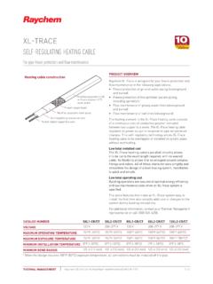
8 You can access the complete warranty on our web site at OVERVIEWThe XL-Trace system provides FREEZE PROTECTION and flow maintenance for aboveground and buried pipe applications. The XL-Trace system is based on self - regulating heating cable technology. Thermal Management offers the option of three self - regulating heating cables with the XL-Trace system: 5XL, 8XL, and 12XL (208 277 V only) for applications using 120 and 208 277 V power supplies. The cable s output is reduced automatically as the pipe warms, so there is no possibility of failure due to XL-Trace system includes the heating cable , power connection, splice, tee connections, controls, contactors, power distribution panels, accessories, and the tools necessary for a complete ApplicationsIdentify which of the standard XL-Trace applications below pertain to your installation.
9 Proceed to the appropriate design sections that 1 XL-TRACE APPLICATIONSA pplicationDescriptionSpecific application requirementsPipe FREEZE protectionGeneral water pipingFreeze PROTECTION (40 F [4 C] minimum) of insulated, metal or plastic water piping Aboveground piping on page 6 Buried piping, page 7 Flow maintenanceGrease waste linesFlow maintenance (110 F [43 C] minimum) for insulated grease waste lines Aboveground piping on page 9 Buried piping on page 10 Fuel linesFlow maintenance (40 F [4 C] minimum) for insulated metal piping containing #2 fuel oil For aboveground piping only, page 11 Note: If your application does not fit these guidelines, contact your local Thermal Management representative or call (800) / 44 THERMAL MANAGEMENTR aychem-DG-H55838-XLTracePipeFreezeFlowMa intCOM-EN-1707 self - regulating heating cable ConstructionRaychem XL-Trace self - regulating heating cables are comprised of two parallel nickel-plated bus wires in a cross-linked polymer core, a tinned copper braid, and a fluoropolymer or polyolefin outer jacket.
10 These cables are cut to length, simplifying the application design and copper bus wireSelf- regulating conductive coreModified polyolefin inner jacketTinned-copper braidPolyolefin orfluoropolymer outer jacketFig. 1 XL-Trace heating cable constructionWith self - regulating technology, the number of electrical paths between bus wires changes in response to temperature fluctuations. As the temperature surrounding the heater decreases, the conductive core contracts microscopically. This contraction decreases electrical resistance and creates numerous electrical paths between the bus wires.