Transcription of PIPING DESIGN, LAYOUT AND STRESS ANALYSIS
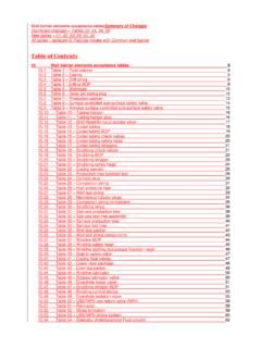
1 NORSOK STANDARDPIPING design , LAYOUT AND STRESS ANALYSISL-002 Rev. 2, September 1997 Please note that every effort has been made to ensure the accuracy of the NORSOK standardsneither OLF nor TBL or any of their members will assume liability for any use design , LAYOUT and STRESS analysisL-002 Rev. 2, September 1997 NORSOK standardPage 1 of 17 CONTENTSFOREWORD21 SCOPE32 NORMATIVE REFERENCES33 DEFINITIONS AND Abbreviations44 design AND Numbering Safety and work Clearance and Pipe Vents, drains and sample Equipment Additional requirements related to PIPING Hook-up Hoses and flexible Instrumentation145 STRESS Selection criteria for lines subject to comprehensive STRESS design Environmental design Bending moment on valves .
2 Flanges and mechanical Flexible Cold Spring Loads from PIPING systems on equipment17 PIPING design , LAYOUT and STRESS analysisL-002 Rev. 2, September 1997 NORSOK standardPage 2 of 17 FOREWORDNORSOK (The competitive standing of the Norwegian offshore sector) is the industry initiative toadd value, reduce cost and lead time and remove unnecessary activities in offshore fielddevelopments and NORSOK standards are developed by the Norwegian petroleum industry as a part of theNORSOK initiative and are jointly issued by OLF (The Norwegian Oil Industry Association) andTBL (Federation of Norwegian Engineering Industries).
3 NORSOK standards are administered byNTS (Norwegian Technology Standards Institution).The purpose of this industry standard is to replace the individual oil company specifications for usein existing and future petroleum industry developments, subject to the individual company's reviewand NORSOK standards make extensive references to international standards. Where relevant, thecontents of this standard will be used to provide input to the international standardisation to implementation into international standards, this NORSOK standard will be design , LAYOUT and STRESS analysisL-002 Rev.
4 2, September 1997 NORSOK standardPage 3 of 171 SCOPEThis standard covers the basis for design and LAYOUT of process, drilling and utility PIPING foroffshore oil and/or gas production facilities. Relevant parts of this standard may also be used forcontrol room, laboratory, helideck and other facilities around the standard does not cover the following:1. All instrument control PIPING downstream of the last PIPING block Risers and sub-sea Sanitary PIPING GRP PIPING . (See NORSOK standard M-621)2 NORMATIVE REFERENCESThe following standards include provisions which, through reference in this text, constituteprovisions of this NORSOK standard.
5 Latest issue of the references shall be used unless otherwiseagreed. Other recognized standards may be used provided it can be shown that they meet or exceedthe requirements of the standards referenced L-001 PIPING and valvesNORSOK L-003 PIPING detail (presently L-CR-003)NORSOK P-001 Process designNORSOK R-001 Mechanical equipmentNORSOK S-001 Technical safetyNORSOK S-002 Working environmentNORSOK Z-002 Coding system (presently Z-DP-002)National and international codes and standards:ASME for flexible pipesISO 5167 Measurement of fluid flowISO 10420 Flexible pipe systems for subsea and marine riser applications(based on API RP 17B)
6 3 DEFINITIONS AND DefinitionsCanCan requirements are conditional and indicates a possibility open to theuser of the ValveAn insulation valve is defined as a valve that is used to shut off a piece ofequipment or system for maintenance purpose design , LAYOUT and STRESS analysisL-002 Rev. 2, September 1997 NORSOK standardPage 4 of 17 MayMay indicates a course of action that is permissible within the limits ofthe standard (a permission).
7 Normative referencesShall mean normative in the application of NORSOK standardsShallShall is an absolute requirement which shall be followed strictly in orderto conform with the is a recommendation. Alternative solutions having the samefunctionality and quality are AbbreviationsThe following abbreviations are given for terms used in this standard:APIA merican Petroleum InstituteASMEThe American Society of Mechanical EngineersDDiameterDNVDet Norske VeritasEDSE lement Data SheetISOI nternational Organization for StandardizationNPSN ominal Pipe SizeNPSHNet Positive Suction Head4 design AND GeneralThe design of all systems shall be in accordance with latest edition of the codes and standards listedin clause 2 Normative conditions shall be in accordance with the ASME except where the requirements ofthis standard are more Numbering
8 SystemsNumbering systems for PIPING , PIPING items and valves shall be in accordance with Safety and work environmentErgonomic consideration shall be taken in design regarding: Tools, valves and control devices, including emergency controls devices shall be accessible. Provision for cleaning, maintenance and repair shall be taken into related to safety and working environment shall conform with source of hazard (release of hydrocarbons), flange joints, shall be located insidehazardous areas as defined in the Area Classification drawings or specification.
9 However, areevaluation of the area classification is still necessary, in order to check for any consequences.(Even if all sources are located inside hazardous area, there might still be a need for extentions).Where applicable, provision shall be made to protect PIPING and equipment from falling design , LAYOUT and STRESS analysisL-002 Rev. 2, September 1997 NORSOK standardPage 5 of Clearance and accessibilityAll PIPING shall be arranged to provide specified headroom and clearances for technical safety, easyoperation, inspection, maintenance and dismantling as stated in attention shall be addressed to clearances required for the removal of pump, compressorand turbine casings and shafts, pump and fan drivers, exchanger bundles, compressor and enginepistons.
10 PIPING shall be kept clear of manholes, access openings, inspection points, hatches, davits,overhead cranes, runway beams, clearance areas for instrument removal, tower dropout areas, accessways and emergency escape vertical clearance of 40 mm is recommended between bottom of skid and deck/floor to , fittings, valve controls, access panels or other equipment shall not extend into escape Pipe ArrangementAll PIPING shall be routed so as to provide a simple, neat and economical LAYOUT , allowing for easysupport and adequate should be arranged on horizontal racks at specific elevations.