Transcription of Power Factor Controller BR6000 - …
1 Power Factor Controller BR6000 . BR6000 -12R. - M128. 1 2 3 4 5 6 7 8 9 10 11 12. Power Factor Controller Blindleistungsregler BR 6000. Auto Program Manual Service Enter OK. cos j Manual Version Power Factor Controller BR 6000. ! CAUTIONS: 1. High voltage ! 2. BR6000 may only be used indoor ! 3. Make sure that the discharge time set in Controller matches capacitor discharge time ! Version E, Jan. 2009. Power Factor Controller BR 6000. CONTENTS. Section 1 General / type series and accessories 3. Section 2 Installation of the Controller / connection diagram 5. Current measurement 6. Programming of phase-correction 6. Alarm output / error messages 7. Section 3 Operating modes 7. Section 4 Automatic operation / display functions 8. Section 5 Programming 9. Automatic initialization 9. Manual programming 10. Programming lock 13. Section 6 Manual operation / Programming of fixed stages 14. Section 7 Service menu, Test run 15. Section 8 Expert mode 16.
2 Expert mode 1. Expert mode 2 18. Section 9 Control principle 19. Section 10 Interface 20. Section 11 Initial operation 20. Section 12 Maintenance and warranty 20. Section 13 Troubleshooting 21. Section 14 Technical data 22. Annex: Annex 1 Table of control series 23. Description of control-series editor Annex 2 Default settings 24. Annex 3 Controller coupling 25. Annex 4 Application MMI6000 26. Annex 5 MODBUS protocol 27. Annex 6 Operating diagram (fast programming) 29. -2- Version E, Jan. 2009. Power Factor Controller BR 6000. Section1 General The Power Factor Controller BR6000 is a modern control device of innovative design with a variety of functions - now in version It is designed for a measuring voltage of (L-N) or (L-L) and a supply voltage of It features a user interface with a menu-driven display in plain text for maximum ease of operation. Straightforward symbols and alphanumeric displays in the language of the country of use (nine languages) combine maximum ease of handling with convenient presentation of results.
3 Display of various grid parameters, storage of various values and a test run option make it easy to analyse errors and monitor the system. An automatic initialization is available which will reduce the commissioning to a minimum. Main features: R Six or 12 switching outputs (depending on the type option for 7 or 13 outputs). R Twenty pre-programmed control series with a self-optimized intelligent control response R Control-series editor for user-defined control series R Complete menu-guided operation and display R Illuminated graphic display with 2 x 16 characters R Four-quadrant operation R Automatic initialization R Display of various line parameters (V, I, F, Q, P, ). R Display of voltage and current harmonics R Display and monitoring of temperature R Monitoring of the individual capacitor Power values R Storage of maximum line-parameter and switching-operation values as well as of the turn-on times of individual capacitor contactors R Manual / automatic operation R Programming of fixed stages and the option of skipping individual outputs R No-voltage turn-off R Error detection for various states and interference-message output R Complete 2nd parameter set programmable / switchable R Test run of PFC system with error analysis R Switchboard-integrated housing 144x144x55 mm Type series and accessories BR6000 -R6 6 relays outputs, 1 alarm relay BR6000 -R12 12 relay outputs, 1 alarm relay Option /F Additional user programmable message relay Input for second parameter set Controller coupling possible (Master-Slave).
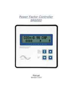
4 Option /S485 Like option /F with additional interface RS485. Accessories - MMI6000 - MultiMeasuringInterface (for measurement of inherent current of capacitor bank ). - Interface converter RS485 to USB for PC-connection - Interface converter RS485 to RS232 for older Pcs -3- Version E, Jan. 2009. Power Factor Controller BR 6000. The Controller is supplied as standard for an operating voltage of VAC (+-15%), a measuring voltage of VAC (L-N) or (L-L) and a measuring current of 5A or 1A. A voltage converter is required for different operating voltages. Caution! ! Voltages which exceed the specified voltage range can damage the device ! BR6000 front view Operating mode - Automatic - Programming - Manual operation - Service BR6000 -12R. - Expert mode - M128. 1 2 3 4 5 6 7 8 9 10 11 12 Enter / OK. Confirm and Power Factor Controller Blindleistungsregler BR 6000 store values Auto Program Increase Manual Service selected parameter Enter OK. cos j Reduce selected parameter Fig.
5 2 BR6000 rear view Power Factor Controller BR6000 -R12. meas. voltage: 30-525 VAC (L-N) or (L-L). supply voltage: 110-230 VAC 50/60Hz : supply- meas. meas. current 1. capacitor- voltage voltage Im (5A/1A) branch Ub Um k l L1 (R). L2 (S). L3 (T). N. PE. T 6,3A. T 2A. T 2A. only BR6000 - 12. Interface *. Ub Um Im P1 P2. K1. Power Factor * option Controller BR6000 . a b 1 2 3 4 5 6 7 8 9 10 11 12. alarm- message external relay relay * input *. capacitor capacitor contactors 1-6 contactors 7-12. supply meas. meas. alarm- voltage voltage current relay 110-230V. L3 L2. (L) (N) (L1) (N) k l a b P1 K1 K2 K3 K4 K5 K6. Interface* Plug1 Interface* Plug2 external message RS485 without input relay Gnd B A SL data logger P2 K7 K8 K9 K10 K11 K12. -4- Version E, Jan. 2009. Power Factor Controller BR 6000. Section 2 Installation and connection of the Controller The BR6000 is designed to be incorporated into the front panel of a PFC-cabinet. It requires a switchboard section of 138 x 138 mm to DIN 43700/ IEC 61554.
6 The Controller is inserted from the front and is attached by means of the appended clamps. The Controller may be inserted only by qualified technicians and must be operated in accordance with the specified safety regulations. Before the BR6000 is connected up, all leads and cables must be checked to ensure that no current is flowing through them and the current converter must be short-circuited. Care should be taken to ensure that the measuring voltage and current are in the correct phase position. The measuring-current circuit must be wired with copper leads of The connection should be set up as shown in Fig. 3. The specified safety regulations must be observed. The measuring voltage may lie in the range from 30 - 525 VAC and can be connected between L - N ( default ) or between L - L (programming of phase correction needed). The operating voltage is VAC +/- 15% and can be connected between L - N or L -L (depending of the grid). The coil voltage for the capacitor contactors and the measuring voltage !
7 Must be drawn from the same phase conductor, as only the measuring voltage is monitored. (Protection against direct reconnection of the capacitor contactors in the event of momentary single-phase Power failure). Fig. 3: BR6000 Connection plan Power feed Load side supply meas. nt 1. capacitor voltage voltage Im (5 A/1A) bra nch Vb Vm k l L1 (R ). L2 (S ). L3 (T ). N. PE. T 6,3A. T 2A. T 2A. only for 12-s tage contro llers (L3) (L2). (L) (N) L1 N k l Interface *. Ub Um Im P1 P2. K1. Power Factor * only option contro ller BR6000 . a b 1 2 3 4 5 6 7 8 9 10 11 12. alarm message external re lay relay* input *. capacitor capacitor contactors 1-6 contactors 7-1 2. -5- Version E, Jan. 2009. Power Factor Controller BR 6000. Current measurement When installing the current converter, care should be taken to ensure that the load current flows through it. The outputs of the compensation network must be installed behind the current converter (in the direction of current flow).
8 If the BR6000 is connected up via sum-current converters, the overall conversion ratio is entered. Current converter clamps should be grounded on one side! Measurement via sum current converter Feed 1 Feed 2. Caution ! ! Current converter clamps should K k k K. be grounded on one side ! L l l L. K L K L. Example: 1: 1000/5A k l 2: 1000/5A. Sum-current converter: 5A+5A/5A k l Current measurement ratio is: 2000/5A BR6000 . Programming of phase-correction - connection directly L-L (400V). Adjustment of phase-correction between voltage and current in the meas. system is done in expert mode 1 (page 17). supply- meas. - voltage voltage Vb L2-L3 k l L1 (R). Example : L2 (S). L3 (T). : L1 N. PE. Meas. Voltage L3-L2. Phase U/I [ 90 ]. T 2A. T 2A. BR6000 . (L) (N) L3 L2 k l Ub Um Im using meas. current meas. voltage phase-angle Preset: L1 L1 - N 0 . L1 L1 - L2 30 . L1 (k<->l) L2 - N 60 . L1 L3 - L2 90 . L1 L3 - N 120 . L1 L3 - L1 150 . L1 (k<->l) L1 - N 180.
9 L1 (k<->l) L1 - L2 210 . L1 L2 - N 240 . L1 L2 - L3 270 . L1 (k<->l) L3 - N 300 . L1 (k<->l) L3 - L1 330 . -6- Version E, Jan. 2009. Power Factor Controller BR 6000. Alarm output / error messages The alarm contact is closed in normal operation and opens in the event of a fault. The relevant fault is simultaneously shown on the display in plain text (alternating with the standard display in automatic operation). The following fault messages are displayed: UNDER-COMPENSATED Display and relay output missing reactive Power OVER-COMPENSATED Display and relay output OVERCURRENT Display and relay output MEASURING VOLTAGE ? Display and relay output OVERTEMPERATURE Display and relay output OVERVOLTAGE Display and relay output UNDERVOLTAGE Display and relay output HARMONICS Display and relay output Additionally several messages for different operation states are generated. An individual adjustment resp. suppression of particular messages is possible in expert mode 2.
10 During suppression, the indication of the message in the display, a possible release via alarm- relays and effects on the controlling process will be prevented. Section 3 Operating modes When the operating voltage is switched on, the BR6000 briefly displays its designation and software version, then changes to its normal operating status (automatic operation). The active cos-phi value is always displayed in the upper line and the currently connected capacitors are shown as symbols in the lower line (operating display). Automatic operation The control direction is symbolized by a closed arrow Display of active Power -line cos phi Display of Fan -option Connecting-in Display of 2nd parameter-set Connecting-out The connecting-in arrow is always located after the maximum possible number of stages (end stop). An open arrow indicates that the Bild: Display voll required blocking time (discharge time) is running before an impending switching step Active capacitor Control direction Supply display (for A double arrow symbolizes fast branches (here connected-in) 4-quadrant operation) switching of several branches Display of activated stages in kvar and in By pressing the cursor Bild: Display % percent of total output of PFC system buttons, the display of capacitor stages can be Display of activated changed: stages as bar-graph Bild: Display Bargraph display in percent of total output of PFC- system The Power values of the individual capacitors are monitored constantly.