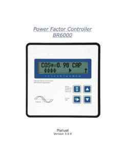
Transcription of Power Factor Controller BR7000-1 (S485)
1 Power Factor ControllerBR7000-1 ( s485 )ManualVersion - Erellortnoc rotcaf rewopnoitareneg txenPower Factor ControllerBR 7000-IAutoProgramManualServiceEnterOKPow er Quality SolutionsHELPESCcos IND 1 2 3 4 5 6 7 8 9 10 11 12jAUTO MODE------------------cosjVersion E, May 2014!CAUTIONS:1. High voltage !2. BR7000-1 may only be used indoor !3. Make sure that the discharge time set in Controller matches capacitor discharge time !UNDERCOMPENSATED----------------------- -------------------------------Q-Diff= 82kvar U I Q 1 2 3 4 5 6 7 8 9 V 268 A 107 kvarHARMONICS [V] 0%AUTO-MODEERROR MESSAGEDISPLAY-MODEBARGRAPH-MODE101112 A MAUTO MODE------------------cos IND 1 2 3 4 5 6 7 8 9 10 11 12 A MjCONTENTSS ection 1 General/ type series and accessories3 Section 2 Installation of the Controller / connection of messages.
2 Alarm- / Message relay7 Section 3 Operating modes 7 Section 4 Automatic operation / display functions8 Section initialization lock13 Section 6 Manual operation / Programming of fixed stages14 Section 7 Service menu, Test run15 Section 8 Expert mode mode 218 Section 9 Control principle19 Section 10 Display editor20 Section 11 Initial operation20 Section 12 Maintenance and warranty20 Section 13 Interface21 Annex:Annex 1 Troubleshouting23 Annex 2 Technical data24 Annex 3 Table of control series25 Description of control-series editorAnnex 4 Default settings26 ApplicationMixed dynamic compensation28 Cascading of controllersApplicationReal current measurement29 Alarm and status notifications30 Handling-diagram / short reference31 ApplicationCoupling of compensation systems27- 2 -Section1 GeneralThe Power Factor Controller BR7000-1 (single phase)
3 Enlarges the product range of Power Factor control devices by a useful combination of the features known from the well-proven series BR6000 with the advantages of a better visualization of the big graphic display enables a user-friendly programming and gives further benefits such as larger display in the Display-mode and the display of various parameters in the additional ESCAPE -button a backward navigation in all menus is HELP -button allows an interactive help in the particular menu item (German/English).The Controller is characterized by its user friendly operating interface via menu driven plain text display. The display of several grid parameters, the storage of different values as well as the possibility of test run allow a simple error analysis and system monitoring.
4 If required, an automatic initialization is possible which reduces the start-up operation to a minimum. R12 respectively 13 switching outputsR20 pre-programmed control series with self optimized intelligent control behaviorRControl series editor for individual control seriesROperation and display completely menu-drivenRIlluminated graphic display 128 x 64 dotsR4 quadrant operationRAutomatic initialization possibleRDisplay of several grid parameters also in large lettersRDisplay of harmonics of voltage and current, also as bar diagramRDisplay and monitoring of temperatureRMonitoring of the particular capacitor outputRStorage of maximum values of grid parameters as well as switching operations and switch-in times of particular capacitor contactorsRManual/automatic operationRProgramming of fixed steps or skipping of single outputs possibleRZero voltage switch offRError display of different states and alarm output (relay)RError storageRTest run of the system with error analysisRPanel-mounted instrument 144 x 144 x 53 mmRFirmware update possibleVersion with interface only.
5 Radditional external input (function programmable), for 2nd parameter setRadditional freely programmable alarm relay, for fan, status notificationRserial interface RS485, for Controller coupling, integration into networksRvisualization, programming and data processing via PC by enclosed software- 3 -The Controller is supplied as standard for an operating voltage of VAC (+-15%), a measuring voltage of V~ (L-N) resp. ~(L-L) and a measuring current of 5A or 1A. A voltage converter is required for different operating !Voltages which exceed the specified voltage range can damage the device !- 4 -!Operating mode:- Automatic- Manual Service- Expert Mode- Osci - Mode- Display EditorENTER/ OKConfirmationstorage ofvaluesIncreaseselected parameterHELP opensHelp pagesReduceselectedparameterEscapeprevio uspage/valuein the display BR 7000-1 front viewHELPESCBR 7000-1 rear viewP1P2K1K7K2K8K3K9K4K10K11K12K13K5K6 L N L1(L3) N (L2)klsupply voltagemeas.
6 Voltagemeas. currentalarmrelayPOWER Factor CONTROLLERBR7000-IL1 (R)L2 (S)L3 (T)N1. capacitor-branch k lP1 P21 2 3 4 5 6 7 8 9 10 11 12capacitor-contactors 1-6alarm-relaycapacitor-contactors 7-12T 6,3AT 2AT 2 APEK113L N L1 N k : MADE IN GERMANY meas. voltage:30-440V(L-N),50-760V(L-L)supply voltage: 50/60 HzType: br7000 -Imeas. currentIm (5A/1A) supply-voltage Vb meas. voltage VmPower Factor ControllerBR 7000-IAutoProgramManualServiceEnterOKPow er Quality SolutionsHELPESC cosjSection 2 Installation and connection of the controllerThe BR7000-1 is designed to be incorporated into the front panel of a PFC-cabinet.
7 It requires a switchboard section of 138 x 138 mm to DIN 43700/ IEC 61554. The Controller is inserted from the front and is attached by means of the appended clamps. The Controller may be inserted only by qualified technicians and must be operated in accordance with the specified safety the device is connected up, all leads and cables must be checked to ensure that no current is flowing through them and the current converter must be short-circuited. Care should be taken to ensure that the measuring voltage and current are in the correct phase 2position. The measuring-current circuit must be wired with copper leads of The connection should be set up as shown below.
8 The specified safety regulations must be measuring voltage may lie in the range from V~ (L-N) resp. ~ (L-L) (programming of phase correction needed)The operating voltage is VAC +/- 15%.The coil voltage for the capacitor contactors and the measuring voltage must be drawn from the same phase conductor, as only the measuring voltage is monitored. (Protection against direct reconnection of the capacitor contactors in the event of momentary single-phase Power failure) BR7000-1 Connection plan- 5 -L1 (R)L2 (S)L3 (T) (5A/1A) 1. capacitorbranch k lP1 P21 2 3 4 5 6 7 8 9 10 11 12capacitorcontactors 1-6alarmrelaycapacitorcontactors 7-12power factorcontroller br7000 -1T 6,3AT 2AT 2 APEK1a bUbUmIm(L) (N) L1 N k l(L3) (L2) Power feed Load side!
9 Current measurementWhen installing the current converter, care should be taken to ensure that the load current and capacitor-current flows through it. The outputs of the compensation network must be installed behind the current converter (in the direction of current flow). If the is connected up via sum-current converters, the overall conversion ratio is Programming of phase-correction - connection directly L-L (400V)Adjustment of phase-correction between voltage and current in the meas. system is done in expert mode 1 Example : L1 Meas. voltage: L3-L2 Phase U/I [ 90 ] - 6 -L1 (R)L2 (S)L3 (T) supply-voltage Vb meas.
10 -voltage L2-L3 k l br7000 -1T 2AT 2 APEUb UmIm(L) (N) L3 L2 k l usingmeas. currentmeas. voltagephase-angle Preset:L1L1 - N 0 L1L1 - L2 30 L1 (k<->l)L2 - N 60 L1L3 - L2 90 L1L3 - N120 L1L3 - L1150 L1 (k<->l)L1 - N180 L1 (k<->l)L1 - L2210 L1L2 - N240 L1 L2 - L3270 L1 (k<->l)L3 - N300 L1 (k<->l)L3 - L1330 kKkKlLlLFeed 1 Feed 2K L K LMeasurement via sum current converterBR7000-1 Currentmeasurementk lk 1: 1000 2: 1000/5 ASum-current converter: 5A+5 ratio is: 2000/5 ADisplay-ModeHarmonics as bar-diagramActive capacitorbranchesControl direction(here connected-in)Supply display (for 4-quadrant operation)The control direction is symbolizedby a closed arrowThe connecting-in arrow is alwayslocated after the maximum possiblenumber of stages (end stop)An open arrow indicates that the required blocking time (dischargetime) is running before an impending switching step A double arrow symbolizes fast switching of several branchesConnecting-inConnecting-outBy pressing the cursor buttons, the display of capacitor stages can be changed.