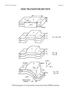
Transcription of Power MOSFET
1 Siliconix S21-0819-Rev. C, 02-Aug-20211 Document Number: 91019 For technical questions, contact: DOCUMENT IS SUBJECT TO CHANGE WITHOUT NOTICE. THE PRODUCTS DESCRIBED HEREIN AND THIS DOCUMENTARE SUBJECT TO SPECIFIC DISCLAIMERS, SET FORTH AT MOSFETFEATURES Dynamic dV/dt rating Repetitive avalanche rated 175 C operating temperature Fast switching Ease of paralleling Simple drive requirements Material categorization: for definitions of compliance please see *This datasheet provides information about parts that are RoHS-compliant and / or parts that are non RoHS-compliant. For example, parts with lead (Pb) terminations are not RoHS-compliant. Please see the information / tables in this datasheet for detailsDESCRIPTIONT hird generation Power MOSFETs from vishay provide the designer with the best combination of fast switching, ruggedized device design, low on-resistance and cost-effectiveness.
2 The TO-220AB package is universally preferred for all commercial-industrial applications at Power dissipation levels to approximately 50 W. The low thermal resistance and low package cost of the TO-220AB contribute to its wide acceptance throughout the Repetitive rating; pulse width limited by maximum junction temperature (see fig. 11)b. VDD = 25 V, starting TJ = 25 C, L = 528 H, Rg = 25 , IAS = 14 A (see fig. 12)c. ISD 14 A, dI/dt 140 A/ s, VDD VDS, TJ 175 Cd. mm from casePRODUCT SUMMARYVDS (V)100 RDS(on) ( )VGS = 10 V max. (nC)26 Qgs (nC) (nC)11 ConfigurationSingleN-Channel MOSFETGDSTO-220 ABGDSA vailableAvailableAvailableORDERING INFORMATIONP ackageTO-220 ABLead (Pb)-freeIRF530 PbFLead (Pb)-free and halogen-freeIRF530 PbF-BE3 ABSOLUTE MAXIMUM RATINGS (TC = 25 C, unless otherwise noted)PARAMETER SYMBOLLIMITUNITD rain-source voltage VDS100V Gate-source voltageVGS 20 Continuous drain currentVGS at 10 VTC = 25 C ID14 ATC = 100 C 10 Pulsed drain current aIDM 56 Linear derating C Single pulse avalanche energy bEAS 69mJ Repetitive avalanche current aIAR 14A Repetitive avalanche energy Maximum Power dissipationTC = 25 C PD88W Peak diode recovery dV/dt cdV/dt Operating junction and storage temperature rangeTJ, Tstg-55 to +175 C Soldering recommendations (peak temperature) dFor 10 s300 Mounting torque6-32 or M3 screw10 lbf Siliconix S21-0819-Rev.
3 C, 02-Aug-20212 Document Number: 91019 For technical questions, contact: DOCUMENT IS SUBJECT TO CHANGE WITHOUT NOTICE. THE PRODUCTS DESCRIBED HEREIN AND THIS DOCUMENTARE SUBJECT TO SPECIFIC DISCLAIMERS, SET FORTH AT Repetitive rating; pulse width limited by maximum junction temperature (see fig. 11)b. Pulse width 300 s; duty cycle 2 %THERMAL RESISTANCE RATINGSPARAMETER junction-to-ambientRthJA-62 C/WCase-to-sink, flat, greased junction-to-case (drain) (TJ = 25 C, unless otherwise noted)PARAMETER SYMBOLTEST CONDITIONS breakdown voltage VDS VGS = 0 V, ID = 250 A 100--V VDS temperature coefficient VDS/TJ Reference to 25 C, ID = 1 mA C Gate-source threshold voltage VGS(th)VDS = VGS, ID = 250 A Gate-source leakage IGSS VGS = 20 V-- 100nA Zero gate voltage drain current IDSS VDS = 100 V, VGS = 0 V --25 A VDS = 80 V, VGS = 0 V, TJ = 150 C --250 Drain-source on-state resistance RDS(on) VGS = 10 VID = A Forward transconductance gfs VDS = 50 V, ID = A DynamicInput capacitance Ciss VGS = 0 V,VDS = 25 V,f = MHz, see fig.
4 5 -670-pFOutput capacitance Coss -250-Reverse transfer capacitance Crss -60-Total gate charge Qg VGS = 10 V ID = 14 A, VDS = 80 V, see fig. 6 and 13 b--26nC Gate-source charge Qgs chargeQgd --11 Turn-on delay time td(on) VDD = 50 V, ID = 14 A Rg = 12 , RD = , see fig. 10 b-10-nsRise timetr -34-Turn-off delay time td(off) -23-Fall time tf -24-Gate input resistanceRgf = 1 MHz, open Internal drain inductance LD Between lead,6 mm ( ") from package and center of die contact Internal source Body Diode CharacteristicsContinuous source-drain diode current ISMOSFET symbolshowing the integral reverse p - n junction diode--14 APulsed diode forward current aISM--56 Body diode voltageVSDTJ = 25 C, IS = 14 A, VGS = 0 V diode reverse recovery timetrrTJ = 25 C, IF = 14 A, dI/dt = 100 A/ s b-150280nsBody diode reverse recovery CForward turn-on timetonIntrinsic turn-on time is negligible (turn-on is dominated by LS and LD) Siliconix S21-0819-Rev.
5 C, 02-Aug-20213 Document Number: 91019 For technical questions, contact: DOCUMENT IS SUBJECT TO CHANGE WITHOUT NOTICE. THE PRODUCTS DESCRIBED HEREIN AND THIS DOCUMENTARE SUBJECT TO SPECIFIC DISCLAIMERS, SET FORTH AT CHARACTERISTICS (25 C, unless otherwise noted) Fig. 1 - Typical Output Characteristics, TC = 25 C Fig. 2 - Typical Output Characteristics, TC = 175 CFig. 3 - Typical Transfer CharacteristicsFig. 4 - Normalized On-Resistance vs. TemperatureFig. 5 - Typical Capacitance vs. Drain-to-Source VoltageFig. 6 - Typical Gate Charge vs. Gate-to-Source Voltage91019_0120 s Pulse WidthTC = 25 VVDS, Drain-to-Source Voltage (V)ID, Drain Current (A)BottomTo pVGS15 V10 V10110010-1100101 VDS, Drain-to-Source Voltage (V)ID, Drain Current (A) V20 s Pulse WidthTC = 175 C91019_02 BottomTo pVGS15 V10 V10110010-110010120 s Pulse WidthVDS = 50 VID, Drain Current (A)VGS, Gate-to-Source Voltage (V)5678910425 C175 C91019_03101100ID = 14 AVGS = 10 60- 40 - 20 0 20 40 60 80 100 120 140 160TJ, Junction Temperature ( C)RDS(on), Drain-to-Source On Resistance(Normalized) (pF)VDS, Drain-to-Source Voltage (V)CissCrssCossVGS = 0 V, f = 1 MHzCiss = Cgs + Cgd, Cds ShortedCrss = CgdCoss = Cds + Cgd91019_05200QG, Total Gate Charge (nC)VGS, Gate-to-Source Voltage (V)2016128040525201510ID = 14 AVDS = 20 VVDS = 50 VFor test circuitsee figure 13 VDS = 80 Siliconix S21-0819-Rev.
6 C, 02-Aug-20214 Document Number: 91019 For technical questions, contact: DOCUMENT IS SUBJECT TO CHANGE WITHOUT NOTICE. THE PRODUCTS DESCRIBED HEREIN AND THIS DOCUMENTARE SUBJECT TO SPECIFIC DISCLAIMERS, SET FORTH AT 7 - Typical Source-Drain Diode Forward VoltageFig. 8 - Maximum Safe Operating AreaFig. 9 - Maximum Drain Current vs. Case TemperatureFig. 10a - Switching Time Test CircuitFig. 10b - Switching Time Waveforms101100 VSD, Source-to-Drain Voltage (V)ISD, Reverse Drain Current (A) C175 CVGS = 0 V91019_0710210 s100 s1 ms10 msOperation in this area limitedby RDS(on)VDS, Drain-to-Source Voltage (V)ID, Drain Current (A)TC = 25 CTJ = 175 CSingle , Drain Current (A)TC, Case Temperature ( C)06810121425150125100755091019_0942175 Pulse width 1 sDuty factor % V+-VDSVDDVDS90 %10 %VGStd(on)trtd(off) Siliconix S21-0819-Rev. C, 02-Aug-20215 Document Number: 91019 For technical questions, contact: DOCUMENT IS SUBJECT TO CHANGE WITHOUT NOTICE.
7 THE PRODUCTS DESCRIBED HEREIN AND THIS DOCUMENTARE SUBJECT TO SPECIFIC DISCLAIMERS, SET FORTH AT 11 - Maximum Effective Transient Thermal Impedance, Junction-to-CaseFig. 12a - Unclamped Inductive Test CircuitFig. 12b - Unclamped Inductive WaveformsFig. 12c - Maximum Avalanche Energy vs. Drain , Rectangular Pulse Duration (s)Thermal Response (ZthJC)Notes:1. Duty Factor, D = t1/t22. Peak Tj = PDM x ZthJC + TCSingle Pulse(Thermal Response)0 - +-VDD10 VVar y tp to obtainrequired IASIASVDSVDDVDStp20004080120160251501251 007550 Starting TJ, Junction Temperature ( C)EAS, Single Pulse Energy (mJ)BottomTo A14 AVDD = 25 Siliconix S21-0819-Rev. C, 02-Aug-20216 Document Number: 91019 For technical questions, contact: DOCUMENT IS SUBJECT TO CHANGE WITHOUT NOTICE. THE PRODUCTS DESCRIBED HEREIN AND THIS DOCUMENTARE SUBJECT TO SPECIFIC DISCLAIMERS, SET FORTH AT 13a - Basic Gate Charge WaveformFig. 13b - Gate Charge Test CircuitFig. 14 - For N-Channel vishay Siliconix maintains worldwide manufacturing capability.
8 Products may be manufactured at one of several qualified locations. Reliability data for Silicon Technology and Package Reliability represent a composite of all qualified locations. For related documents such as package/tape drawings, part marking, and reliability data, see F50 k 12 VCurrent regulatorCurrent sampling resistorsSame type as + recoverydV/dtRipple 5 %Body diode forward dropRe-appliedvoltageReverserecoverycurr entBody diode forwardcurrentVGS = 10 Va ISDD river gate lSD VDS waveformInductor currentD = +-+++---Peak Diode Recovery dV/dt Test CircuitVDD dV/dt controlled by Rg Driver same type as ISD controlled by duty factor D - device under layout considerations Low stray inductance Ground plane Low leakage inductancecurrent transformerRgNotea. VGS = 5 V for logic level devicesVDDL egal Disclaimer Revision: 01-Jan-20231 Document Number: 91000 Disclaimer ALL PRODUCT, PRODUCT SPECIFICATIONS AND DATA ARE SUBJECT TO CHANGE WITHOUT NOTICE TO IMPROVE RELIABILITY, FUNCTION OR DESIGN OR OTHERWISE.
9 vishay Intertechnology, Inc., its affiliates, agents, and employees, and all persons acting on its or their behalf (collectively, vishay ), disclaim any and all liability for any errors, inaccuracies or incompleteness contained in any datasheet or in any other disclosure relating to any makes no warranty, representation or guarantee regarding the suitability of the products for any particular purpose or the continuing production of any product. To the maximum extent permitted by applicable law, vishay disclaims (i) any and all liability arising out of the application or use of any product, (ii) any and all liability, including without limitation special, consequential or incidental damages, and (iii) any and all implied warranties, including warranties of fitness for particular purpose, non-infringement and regarding the suitability of products for certain types of applications are based on vishay 's knowledge of typical requirements that are often placed on vishay products in generic applications.
10 Such statements are not binding statements about the suitability of products for a particular application. It is the customer's responsibility to validate that a particular product with the properties described in the product specification is suitable for use in a particular application. Parameters provided in datasheets and / or specifications may vary in different applications and performance may vary over time. All operating parameters, including typical parameters, must be validated for each customer application by the customer's technical experts. Product specifications do not expand or otherwise modify vishay 's terms and conditions of purchase, including but not limited to the warranty expressed included in this datasheet may direct users to third-party websites. These links are provided as a convenience and for informational purposes only. Inclusion of these hyperlinks does not constitute an endorsement or an approval by vishay of any of the products, services or opinions of the corporation, organization or individual associated with the third-party website.