Transcription of Principles of Data Acquisition and Conversion (Rev. A)
1 1 SBAA051A January1994 RevisedApril2015 SubmitDocumentationFeedbackCopyright 1994 2015,TexasInstrumentsIncorporatedPrincip lesof DataAcquisitionand ConversionApplicationReportSBAA051A January1994 RevisedApril2015 Principlesof DataAcquisitionand ConversionABSTRACTD ataacquisitionand conversionsystemsare usedto acquireanalogsignalsfromone or moresourcesand convertthesesignalsinto digitalformfor analysisor transmissionby end devicessuchas digitalcomputers,recorders,or analogsignalinputsto dataacquisitionsystemsare mostoftengeneratedfromsensorsand transducerswhichconvertreal-worldparamet erssuchaspressure,temperature,stressor strain,flow,etc, thenconvertedby the dataacquisitionsystemand are thenutilizedby the enddevicesin abilityof the electronicsystemto preservesignalaccuracyand integrityis themainmeasureof the qualityof the basiccomponentsrequiredfor the acquisitionand conversionof analogsignalsinto equivalentdigitalformare the following: AnalogMultiplexerand SignalConditioning Sample/HoldAmplifier Analog-to-DigitalConverter Timingor SequenceLogicTypically,today s dataacquisitionsystemscontainall the elementsneededfor dataacquisitionandconversion,exceptperha ps,for inputfilteringand signalconditioningpriorto timemultiplexedby the analogmultiplier.
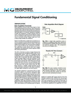
2 The multiplexeroutputsignalis thenusuallyappliedto a very-linearfast-settlingdifferentialampl ifierand/orto a fast-settlinglow sample/holdis programmedto acquireand hold eachmultiplexeddatasamplewhichis convertedintodigitalformby an A/D thenpresentedat the outputof the A/Dconverterin paralleland serialdigitalformfor furtherprocessingby the end Cycle?.. Few A/D trademarksare the propertyof OrderInterpolation(Reconstruction UsingFilter or Vector Generator)Zero OrderInterpolation(Reconstruction Directlyfrom D/A Converter)ReconstructedWave FormOriginal SignalAliasing Error(not enough samples per frequency cycle f < 2f)SMAXN umber ofSamples/CycleMinimumSystemSamplingRate NumberofChannelsHighestBandwidthData January1994 RevisedApril2015 SubmitDocumentationFeedbackCopyright 1994 2015,TexasInstrumentsIncorporatedPrincip lesof DataAcquisitionand applicationand ultimateuse of the converteddatadeterminesthe requiredsamplingand conversionrate of the dataacquisitionand is determined,as showninFigure1, by the highestbandwidthchannel,the numberof datachannelsand the numberof Nyquistsamplingtheorem,a minimumof two samplesper cycleof the databandwidthisrequiredin an idealsampleddatasystemto reproducesampleddatawith no loss of ,thefirst considerationfor determiningsystemsamplingrate is aliasingerror.
3 Errorsdue to informationbeinglost by not takinga sufficientnumberof samplesper cycleof illustratesaliasingerrorcausedfroman insufficientnumberof samplesper cycleof AliasingErrorvs Cycle?The answerto this questiondependson the allowableaverageerrortolerance,the methodofreconstruction(if any),and the end use of the the end use, the actualerrorof thediscretedatasampleswill be equalto the throughputerrorof the dataacquisitionand conversionsystemplus any digitalerrorscontributedby a digitalcomputeror otherdigitalend (%)First Order DataReconstruction(Vector Connectionof Sample)Zero Order DataReconstruction(D/A ConverterOutput)(1)(1)(1)(1)(1)(1)Note: (1) data samples of conversionsystem (2 samples per cycle).
4 OriginalDataSignal(a)Zero OrderReconstructedData(D/A ConverterOutput)(b)First OrderDataReconstruction(Filtered DACor Vector Generator) January1994 RevisedApril2015 SubmitDocumentationFeedbackCopyright 1994 2015,TexasInstrumentsIncorporatedPrincip lesof DataAcquisitionand ConversionFor incrementaldevicessuchas steppingmotorsand switches,the averageerrorof sampleddigitaldatais not as importantas it is for end devicesthat illustrateaveragesamplingerrorin sampleddatasystems,considerthe casewherethe minimumof 2 samplesper cycleofsinusoidaldataare taken,and the datais reconstructeddirectlyfroman unfilteredD/A converter(zero-orderreconstruction).The averageerrorbetweenthe reconstructeddataand the originalsignalis one-halfthe differencein areafor one-halfcycledividedby , or 32%for zeroorderdata,and 14%for first ,the instantaneousaccuracyat eachsamplepointis equalto the accuracyof theacquisitionand conversionsystem,and in manyapplications,this may be sufficientfor drivingband-limitedend averageaccuracyof sampleddatacan be improvedby (1) increasingthe numberofsamplesper cycle;(2) presamplefilteringpriorto multiplexing,or (3) filteringthe D/A Reconstructionof SampledDataWherefS= 2fMAXThe improvementin averageaccuracyof sampleddatais dramaticwith only a slightincreasein thenumberof samplesper cycleas shownin Figure4.
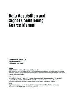
5 The theoreticallimit is the throughputaccuracyof theacquisitionand conversionsystemfor ReconstructionAccuracyvs Numberof SamplesPer CycleFor zeroorderreconstructionof data ,it can be seenfromFigure4 that morethan10 samplesper cycleofdatabandwidthare requiredto reconstructsampleddatato averageaccuraciesof 90%or 7 to 10 samplesper Time (ns)1011 Error (% Full-Scale Range)1/2 LSB of 10 Bits1/2 LSB of 12 Bits1/2 LSB of 13 Bits1/2 LSB of 16 Bits1/2 LSB of 14 Bits10Hz100Hz1kHz10kHz100kHz1 MHz()AAA sin 2 ftAperture Error dt 100% 2 ft 100%maxdtp= = p January1994 RevisedApril2015 SubmitDocumentationFeedbackCopyright 1994 2015,TexasInstrumentsIncorporatedPrincip lesof DataAcquisitionand definedas the amplitudeand time errorsof the sampleddatapointsdue to theuncertaintyof the dataacquisitionand conversionsystems,apertureerrorcan be reducedor madeinsignificanteitherby the use of a sample/holdor with a very fastA/D sinusoidaldata,maximumapertureerroroccur sat the zerocrossingwherethe greatestdV/dtoccurs,and is expressedmathematicallyas.
6 Where f = maximumdatafrequency tA= aperturetime of system(Thiscan be the conversiontime of the A/D converterwith no sample/hold,orthe aperturetime of a sample/holdif one is in frontof an A/D converter.)(1)This expressionis showngraphicallyin Figure5 for frequenciesof 1 Hz to 10 kHz with 1/2 LSB errorhighlightedfor 8-, 10- and 12-bitresolutionA/D needfor a sample/holdbecomesreadilyapparentwhendat afrequenciesof 10 Hz or higherare sampled,becausethe A/D converterconversionspeedmustbe 2 s or fasterfor apertureerrorsless than l/2 LSB for l2-bitresolution,and high speedA/D convertersare complicatedand expensivewhencomparedto slowerA/D converterswith a ApertureErrorvs ApertureTimefor DataFrequenciesfrom10 Hzto 1 MHzA sample/hold with an aperturetime of 50nsto 60nsproducesnegligibleapertureerrorfor datafrequenciesup to 100 Hz for 10- and 12-bitresolutionA/ D converters.
7 And is less than 1/2 LSB for 8-bitresolutionfor datafrequenciesnear5 Figure5 to determineyoursystemapertureerrorfor eachdatachannelversusthe FewA/D ConverterPointsA briefdiscussionof A/D converterterminologywill help the readerunderstandsystemresolutionandaccur acya little analogvaluesare presumedto existat the inputto the A/D A/D converterquantizesorencodesspecificvalue sof the analoginputinto equivalentdigitalcodesas an inherentuncertaintyor quantizationerrorof 1 , the quantizeddigitalcoderepresentsan analogvoltagethat can be anywherewithin 1/2 LSBfromthe A/D convertercan neverbe moreaccuratethanthe inherant 1 gain,offset,and linearityerrorsalso affectA/D ,gainand offseterrorscan be trimmedto zero,but linearityerroris not adjustablebecauseit is causedby thefixed-valueladderresistornetworkand convertershavelessFSRFSRnDVVR esolution One LSB, for binary A / D converters, for decimal A / D converters210=== Few A/D ConverterPoints5 SBAA051A January1994 RevisedApril2015 SubmitDocumentationFeedbackCopyright 1994 2015.
8 TexasInstrumentsIncorporatedPrinciplesof DataAcquisitionand Conversionthan 1 size ofstepsbetweenadjacenttransitionpointsin an idealA/D converteris one differencebetweenadjacenttransitionpoint sin an actualA/D converterand an idealone LSB errormustbe less thanone LSB in orderto guaranteethat thereare no A/Dconverterwith 1/2 LSB linearityerrordoesnot necessarilyimplythat thereare no ResolutionThe numberof bits in the A/D converterdeterminesthe resolutionof the the channel(s)havingthe widestdynamicrangeand/orthe channel(s)that requiremeasurementof the example,assumea channelthat measurespressurehas a dynamicrangeof 4000psithat mustbe measuredto the will requirean A/Dconverterwith a minimumresolutionof 12-bitA/D converterwill providea resolutionof 212or 4096codes adequatefor this actualresolutionof this channelwill be4000/4096or A/D convertercan resolvethis measurementto within ( 1/2 LSB).
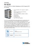
9 Numberof bits in an A/D converterdeterminesthe resolutionof the definedas:where LSB = leastsignificantbit VFSR= full scaleinputvoltagerange n = numberof bits D = numberof decimaldigits(2)The numberof bits definesthe numberof digitalcodesand is 2ndiscretedigitalcodesfor A/D this discussion,we will use binarysuccessive-approximationA/D showsresolutionsand LSB valuesfor typicalA/D Relationshipof A/D ConverterLSBV aluesand Resolutionsfor BinaryCodesA/D ConverterResolution(BinaryCode)Valueof 1 LSBV alueof 1/2 LSBN umberofBits (n)Numberof Increments(2n)0 to 10 V Range(mV)10 V Range(mV)0 to 10 V Range(mV)10 V Range(mV) throughputrate of the systemis determinedby the settlingtimesrequiredin the analogmultiplexerand inputamplifier,sample/holdacquisitiontim e and A/D convertersettlingand programmingmodesthat are commonlyusedin dataacquisitionsystemsare normalserialprogramming(Figure6) and overlapmodeprogramming(Figure7).
10 The rangeof typicalsystemthroughputratesfor thesetypesof modesare shownin Table2 for the e+ e+ e+ eChannel PeriodChannel InChannel PeriodChannel InMultiplierand AmplifierSettlingTimeS/HAcquisi-tion andSettlingTimeA/D ConverterSettling andConversion January1994 RevisedApril2015 SubmitDocumentationFeedbackCopyright 1994 2015,TexasInstrumentsIncorporatedPrincip lesof DataAcquisitionand ConversionA widerangeof throughputspeedscan be achievedby shortcycling the A/D converterto lowerresolutionsand by overlapprogrammingthe multiplexerand amplifiersettlingtime is eliminatedby selectingthe next sample(channeln + 1) whilethe held sample(channeln) is requiresa sample/holdwith very low SystemThroughputRate-SignalProgrammingFi gure7.