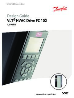
Transcription of Programming Guide PROFINET - Danfoss
1 ENGINEERING TOMORROWP rogramming GuidePROFINETVLT AutomationDrive FC Purpose of the Additional Document and Software Product Approvals and Symbols, Abbreviations, and Conventions42 Safety Qualified Safety Precautions53 Configure the PROFINET Configure the Configure the Frequency Converter94 PPO Process Control PROFI drive Control FC Drive Control Profile185 Acyclic Communication (DP-V1) Features of an IO Controller Features of an IO Supervisor Addressing Acyclic Read/Write Request Data Structure in the Acyclic Parameter Data Block246 Parameter Group 0-** Parameter Group 8-** Communication and Parameter Group 9-** Parameter Group 12-** PROFINET -specific Parameters34 ContentsProgramming GuideMG06G102 Danfoss A/S 04/2017 All rights Supported Object and Data Types387 Application Example: Process Data with PPO Type Example: Control Word telegram Using Standard telegram 1 Example.
2 Status Word telegram Using Standard telegram 1 Example: PLC Example: PLC and Network Monitoring448 No Response to Control Warnings and Warning/Alarm Messages52 Index57 ContentsPROFINET2 Danfoss A/S 04/2017 All rights Purpose of the ManualThe PROFINET Programming Guide provides informationabout configuring the system, controlling the frequencyconverter, accessing parameters, Programming , trouble-shooting, and some typical application Programming Guide is intended for use by qualifiedpersonnel, who are familiar with the VLT frequencyconverters, PROFINET technology.
3 And the PC or PLC that isused as a master in the the instructions before Programming and follow theprocedures in this is a registered Additional ResourcesResources available for the frequency converter andoptional equipment are: The VLT AutomationDrive FC 360 Quick Guideprovides the necessary information for gettingthe frequency converter up and running. The VLT AutomationDrive FC 360 Design Guideprovides detailed information about capabilitiesand functionality to design motor controlsystems. The VLT AutomationDrive FC 360 ProgrammingGuide provides more details on working withparameters and many application publications and manuals are availablefrom Danfoss .
4 See for Document and Software VersionThis manual is regularly reviewed and updated. Allsuggestions for improvement are welcome. Table showsthe document version and the corresponding softwareversion. The firmware version of the PROFINET interfacecan be read in parameter 15-61 Option SW first edition of this Document and Software Product OverviewThis Programming Guide relates to PROFINET interface forVLT AutomationDrive FC PROFINET interface is designed to communicate withany system complying with the PROFINET schema and the introduction in 2001, PROFINET has beenupdated to handle low and medium performancerequirements supported by PROFINET RT up to high-endservo performance in PROFINET IRT.
5 PROFINET is theEthernet-based fieldbus offering and is the most scalableand versatile technology provides the network tools to deploy standardEthernet technology for manufacturing applications whileenabling Internet and enterprise PROFINET control cassette is intended for use withVLT AutomationDrive FC this manual, several terms for Ethernet are used. PROFINET is the term used to describe thePROFINET protocol. Ethernet is a common term used to describe thephysical layer of the network, and does not relateto the application GuideMG06G102 Danfoss A/S 04/2017 All rights Approvals and CertificationsMore approvals and certifications are available.
6 For moreinformation, contact a local Danfoss Symbols, Abbreviations, andConventionsAbbreviationDefinitionCCCo ntrol cardCTWC ontrol wordDCPD iscovery and configuration protocolDHCPD ynamic host configuration protocolEMCE lectromagnetic compatibilityGSDMLG eneral station description mark-up languageI/OInput/outputIPInternet protocolIRTI sochronous real timeLCPL ocal control panelLEDL ight emitting diodeLSBL east significant bitMAVMain actual value (actual speed)MSBMost significant bitMRVMain reference valuePCPersonal computerPCDP rocess control dataPLCP rogrammable logic controllerPNUP arameter numberPPOP rocess parameter objectREFR eference (= MRV)RTReal timeSTWS tatus wordTable Symbols and AbbreviationsConventionsNumbered lists indicate lists indicate other information and description text indicates: Cross reference.
7 Link. Parameter name. Parameter group. Parameter A/S 04/2017 All rights Safety SymbolsThe following symbols are used in this Guide :WARNINGI ndicates a potentially hazardous situation that couldresult in death or serious a potentially hazardous situation that couldresult in minor or moderate injury. It can also be used toalert against unsafe important information, including situations thatcan result in damage to equipment or Qualified PersonnelCorrect and reliable transport, storage, installation,operation, and maintenance are required for the trouble-free and safe operation of the frequency converter.
8 Onlyqualified personnel are allowed to install or operate personnel are defined as trained staff, who areauthorized to install, commission, and maintain equipment,systems, and circuits in accordance with pertinent laws andregulations. Additionally, the qualified personnel must befamiliar with the instructions and safety measuresdescribed in this Safety PrecautionsWARNINGHIGH VOLTAGEF requency converters contain high voltage whenconnected to AC mains input, DC supply, or load to perform installation, start-up, and maintenanceby qualified personnel can result in death or seriousinjury.
9 Only qualified personnel must perform instal-lation, start-up, and STARTWhen the frequency converter is connected to AC mains,DC supply, or load sharing, the motor can start at anytime. Unintended start during Programming , service, orrepair work can result in death, serious injury, orproperty damage. The motor can start with an externalswitch, a fieldbus command, an input reference signalfrom the LCP or LOP, via remote operation using MCT 10 Set-up Software, or after a cleared fault prevent unintended motor start: Press [Off/Reset] on the LCP beforeprogramming parameters.
10 Disconnect the frequency converter from themains. Completely wire and assemble the frequencyconverter, motor, and any driven equipmentbefore connecting the frequency converter toAC mains, DC supply, or load TIMEThe frequency converter contains DC-link capacitors,which can remain charged even when the frequencyconverter is not powered. High voltage can be presenteven when the warning LED indicator lights are to wait the specified time after power has beenremoved before performing service or repair work canresult in death or serious injury. Stop the motor.
