Transcription of Programming Guide VLT AQUA Drive FC 202 Software …
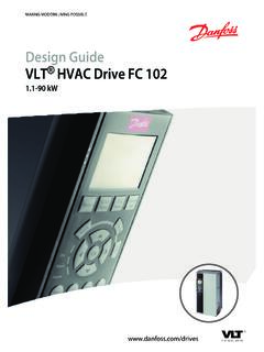
1 ENGINEERING TOMORROWP rogramming GuideVLT aqua Drive FC 202 Software version: Purpose of the Additional Software Frequency Abbreviations, Symbols, and Electrical Wiring102 How to The Graphical and Numerical Local Control How to Program on the Graphical The LCP Quick Transfer of Parameter Settings between Multiple Frequency Display Display Mode - Selection of Parameter Quick Menu Key Quick Menu, Q3 Function Quick Menu, Q4 Main Menu Parameter Changing Changing a Text Changing a Data Infinitely Variable Change of Numeric Data Value, Step by Readout and Programming of Indexed How to Program on the Numerical Local Control LCP Keys243 Parameter Parameter Selection26 ContentsProgramming GuideMG20OB02 Danfoss A/S 05/2018 All rights Parameters 0-** Operation and Parameters 1-** Load and Parameters 2-** Parameters 3-** Parameters 4-** Parameters 5-** Digital Parameters 6-** Analog Parameters 8-** Communications and Parameters 9-** Parameters 10-** CAN Parameters 13-** Smart Parameters 14-** Special Parameters 15-** Drive Parameters 16-** Data Parameters 18-** Data Readouts Parameters 20-** FC Closed Parameters 21-** Extended Closed Parameters 22-** Application Parameters 23-** Time-based Parameters 24-** Application
2 Functions Parameters 25-** Cascade Parameters 26-** Analog I/O Option MCB Parameters 27-** Cascade CTL Parameters 29-** Water Application Parameters 30-** Special Parameters 31-** Bypass Parameters 35-** Sensor Input Option2454 Parameter Parameter Default 0-** 1-** Load and 2-** 3-** 4-** 5-** Digital 6-** Analog 8-** Comm. and 9-** 10-** CAN Fieldbus262 ContentsVLT aqua Drive FC 2022 Danfoss A/S 05/2018 All rights 13-** Smart 14-** Special 15-** Drive 16-** Data 18-** Info & 20-** Drive Closed 21-** Ext. Closed 22-** Appl. 23-** Time-based 24-** Appl. Functions 25-** Cascade 26-** Analog I/O 29-** Water Application 30-** Special 31-** Bypass 35-** Sensor Input Option2815 Status Warnings/Alarm Messages283 Index289 ContentsProgramming GuideMG20OB02 Danfoss A/S 05/2018 All rights Purpose of the ManualThe Programming Guide provides information required forprogramming the frequency converter in a diversity is a registered Additional ResourcesOther resources are available to understand advancedfrequency converter functions and Programming .
3 The VLT aqua Drive FC 202 Operating Instructionsdescribe mechanical and electrical installation ofthe frequency converter. The VLT aqua Drive FC 202 Design Guideprovides detailed information about capabilitiesand functionality to design motor controlsystems. Instructions for operation with publications and manuals are availablefrom Danfoss. See for Software VersionSoftware version: Software version number can be read from parameter 15-43 Software SymbolsThe following symbols are used in this Guide :WARNINGI ndicates a potentially hazardous situation that couldresult in death or serious a potentially hazardous situation that couldresult in minor or moderate injury. It can also be used toalert against unsafe important information, including situations thatcan result in damage to equipment or ConverterIVLT,MAXM aximum output ,NRated output current supplied by the frequency ,MAXM aximum output commandStart and stop the connected motor with LCP and are divided into 2 in group 1 have higher priority than functions ingroup 1 Reset, coast stop, reset and coast stop, quick stop,DC brake, stop, the [OFF] 2 Start, pulse start, reversing, start reversing, jog,freeze Function runningTorque generated on output shaft and speed from 0 RPMto maximum speed on frequency when the jog function is activated (viadigital terminals).
4 FMMotor motor motor aqua Drive FC 2024 Danfoss A/S 05/2018 All rights ,NRated motor frequency (nameplate data).IMMotor current (actual).IM,NRated motor current (nameplate data).nM,NNominal motor speed (nameplate data).nsSynchronous motor par. 1 23 60 spar. 1 39nslipMotor ,NRated motor power (nameplate data in kW or hp).TM,NRated torque (motor).UMInstant motor ,NRated motor voltage (nameplate data).Break-away Break-away Torque VLTThe efficiency of the frequency converter is defined as theratio between the power output and the power commandA stop command belonging to Group 1 control commands- see Table commandA stop command belonging to Group 1 control commands- see Table referenceA signal transmitted to the analog inputs 53 or 54 (voltageor current).
5 Binary referenceA signal transmitted to the serial communication referenceA defined preset reference to be set from -100% to +100%of the reference range. Selection of 8 preset references viathe digital referenceA pulse frequency signal transmitted to the digital inputs(terminal 29 or 33).RefMAXD etermines the relationship between the reference input at100% full scale value (typically 10 V, 20 mA) and theresulting reference. The maximum reference value is set inparameter 3-03 Maximum the relationship between the reference input at0% value (typically 0 V, 0 mA, 4 mA) and the resultingreference. The minimum reference value is set inparameter 3-02 Minimum inputsThe analog inputs are used for controlling variousfunctions of the frequency are 2 types of analog inputs:Current input, 0 20 mA, and 4 20 mAVoltage input, -10 V DC to +10 V outputsThe analog outputs can supply a signal of 0 20 mA, 4 motor adaptation, AMAThe AMA algorithm determines the electrical parametersfor the connected motor at resistorThe brake resistor is a module capable of absorbing thebrake power generated in regenerative braking.
6 Thisregenerative brake power increases the DC-link voltageand a brake chopper ensures that the power is transmittedto the brake characteristicsConstant torque characteristics used for all applicationssuch as conveyor belts, displacement pumps, and inputsThe digital inputs can be used for controlling variousfunctions of the frequency GuideMG20OB02 Danfoss A/S 05/2018 All rights outputsThe frequency converter features 2 solid-state outputs thatcan supply a 24 V DC (maximum 40 mA) signal thermal relay is a thermal load calculation basedon present load and time. Its purpose is to estimate themotor HIPERFACE is a registered trademark by initializing is carried out (parameter 14-22 OperationMode), the frequency converter returns to the duty cycleAn intermittent duty rating refers to a sequence of dutycycles.
7 Each cycle consists of an on-load and an off-loadperiod. The operation can be either periodic duty or non-periodic local control panel makes up a complete interface forcontrol and Programming of the frequency converter. Thecontrol panel is detachable and can be installed up to 3 m(10 ft) from the frequency converter, that is, in a frontpanel with the installation kit local control panel interface for control andprogramming of the frequency converter. The display isnumerical and the panel is used to show process NLCP has no storage and copy significant significant for mille circular mil, an American measuring unit forcable cross-section. 1 MCM= parametersChanges to online parameters are activated immediatelyafter the data value is changed.
8 Press [OK] to activatechanges to off-line PIDThe PID control maintains the required speed, pressure,temperature, and so on, by adjusting the output frequencyto match the varying control cycleSwitch off the mains until the display (LCP) is dark, thenturn power on input/incremental encoderAn external, digital pulse transmitter used for feeding backinformation on motor speed. The encoder is used inapplications where great accuracy in speed control current parameter settings in 4 set-ups. Change between the4 parameter set-ups and edit 1 set-up, while another set-up is pattern called stator flux-oriented asynchronousvector modulation (parameter 14-00 Switching Pattern).Slip compensationThe frequency converter compensates for the motor slip bygiving the frequency a supplement that follows themeasured motor load keeping the motor speed SLC (smart logic control) is a sequence of user-definedactions executed when the associated user-defined eventsare evaluated as true by the SLC.
9 (See chapter Parameters 13-** Smart Logic).STWS tatus standard busIncludes RS485 bus with FC protocol or MC protocol. Seeparameter 8-30 harmonic distortion states the total contribution temperature-dependent resistor placed on the frequencyconverter or the state entered in fault situations, for example if thefrequency converter is subject to an overtemperature orwhen the frequency converter is protecting the motor,process, or mechanism. The frequency converter prevents arestart until the cause of the fault has disappeared. Tocancel the trip state, restart the frequency converter. Donot use the trip state for personal lockThe frequency converter enters this state in fault situationsto protect itself. The frequency converter requires physicalintervention, for example when there is a short circuit onthe output.
10 A trip lock can only be canceled by discon-necting mains, removing the cause of the fault, andreconnecting the frequency converter. Restart is preventeduntil the trip state is canceled by activating reset or,sometimes, by being programmed to reset not use the trip lock state for personal aqua Drive FC 2026 Danfoss A/S 05/2018 All rights characteristicsVariable torque characteristics used for pumps and +If compared with standard voltage/frequency ratio control,voltage vector control (VVC+) improves the dynamics andthe stability, both when the speed reference is changedand in relation to the load AVM60 asynchronous vector modulation(parameter 14-00 Switching Pattern).Power factorThe power factor is the relation between I1 and factor = 3 x U x I1 cos 3 x U x IRMSThe power factor for 3-phase control:Power factor = I1 x cos 1 IRMS = I1 IRMS since cos 1 = 1 The power factor indicates to which extent the frequencyconverter imposes a load on the mains lower the power factor, the higher the IRMS for thesame kW performance.