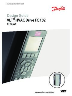
Transcription of Programming Guide VLT HVAC Basic Drive FC 101 - Danfoss
1 ENGINEERING TOMORROWP rogramming GuideVLT hvac Basic Drive FC Purpose of the Document and Software Safety Safety Additional Electrical Overview82 Local Control Panel (LCP) Status Quick Main Quick Transfer of Parameter Settings between Multiple Frequency Readout and Programming of Indexed Initialization to Default Settings253 Main Menu - Operation and Display - Group Main Menu - Load and Motor - Group Main Menu - Brakes - Group Main Menu reference /Ramps Group Main Menu - Limits/Warnings - Group Main Menu - Digital In/Out - Group Main Menu - Analog In/Out - Group Main Menu - Communications and Options - Group Main Menu - Smart Logic - Group Main Menu - Special Functions - Group Main Menu - Drive Information - Group Main Menu - Data Readouts - Group Main Menu - Data Readouts 2 - Group Main Menu - FC Closed Loop - Group Main Menu - Application Functions - Group Main Menu - Application Functions 2 - Group Main Menu - Special Features - Group 30974
2 Troubleshooting98 ContentsProgramming GuideMG18B502 Danfoss A/S 04/2018 All rights Introduction to Alarms and Alarm Warning Extended Status List of Warnings and List of LCP Errors1045 Parameter Parameter Default 0-** 1-** Load and 2-** 3-** 4-** 5-** Digital 6-** Analog 8-** Comm. and 13-** Smart 14-** Special 15-** Drive 16-** Data 18-** Info & 20-** Drive Closed 22-** Appl. 24-** Appl. Functions 30-** Special Features117 Index118 ContentsVLT hvac Basic Drive FC 1012 Danfoss A/S 04/2018 All rights Purpose of the ManualThis Programming Guide provides information for advance-Menusd Programming of the frequency converter. Itprovides a complete overview of all parameters anddescriptions for all Programming Guide is intended for use by operate the frequency converter safely and profes-sionally, read and follow the Programming Guide , and payparticular attention to the safety instructions and Document and Software VersionThis manual is regularly reviewed and updated.
3 Allsuggestions for improvement are versionMG18B5xxUpdate to newsoftware Document and Software VersionFrom software version and later (production week 332017 and after), the variable speed heat sink cooling fanfunction is implemented in the frequency converter forpower sizes 22 kW (30 hp) 400 V IP20 and below, and (25 hp) 400 V IP54 and below. This function requiressoftware and hardware updates and introduces restrictionswith regards to backwards compatibility for H1 H5 and I2 I4 enclosure sizes. Refer to Table for the control card(production week33 2017 or before)New control card(production week34 2017 or after)Old software(OSS-file version below)YesNoNew software(OSS-file version higher)NoYesHardwarecompatibilityOld control card(production week33 2017 or before)New control card(production week34 2017 or after)Old power card(production week 332017 or before)Yes (only softwareversion orbelow)Yes (MUST updatesoftware to or higher)New power card(production week 342017 or after)Yes (MUST updatesoftware to or below, thefan continuouslyruns at full speed)Yes (only softwareversion orhigher)Table Software and Hardware Safety SymbolsThe following symbols are used in this Guide .
4 WARNINGI ndicates a potentially hazardous situation that couldresult in death or serious a potentially hazardous situation that couldresult in minor or moderate injury. It can also be used toalert against unsafe important information, including situations thatcan result in damage to equipment or GuideMG18B502 Danfoss A/S 04/2018 All rights Safety PrecautionsWARNINGHIGH VOLTAGEF requency converters contain high voltage whenconnected to AC mains input, DC supply, or load to perform installation, start-up, and maintenanceby qualified personnel can result in death or seriousinjury. Only qualified personnel must perform instal-lation, start-up, and maintenance. Before performing any service or repair work,use an appropriate voltage measuring device tomake sure that there is no remaining voltage onthe frequency STARTWhen the Drive is connected to AC mains, DC supply, orload sharing, the motor can start at any start during Programming , service, or repairwork can result in death, serious injury, or propertydamage.
5 The motor can start with an external switch, afieldbus command, an input reference signal from theLCP or LOP, via remote operation using MCT 10 SetupSoftware, or after a cleared fault prevent unintended motor start: Press [Off/Reset] on the LCP beforeprogramming parameters. Disconnect the Drive from the mains. Completely wire and assemble the Drive , motor,and any driven equipment before connectingthe Drive to AC mains, DC supply, or TIMEThe frequency converter contains DC-link capacitors,which can remain charged even when the frequencyconverter is not powered. High voltage can be presenteven when the warning LED indicator lights are to wait the specified time after power has beenremoved before performing service or repair work canresult in death or serious injury. Stop the motor. Disconnect AC mains and remote DC-link powersupplies, including battery back-ups, UPS, andDC-link connections to other frequencyconverters.
6 Disconnect or lock PM motor. Wait for the capacitors to discharge fully. Theminimum duration of waiting time is specifiedin Table Before performing any service or repair work,use an appropriate voltage measuring device tomake sure that the capacitors are [V]Power range [kW (hp)]Minimum waiting time(minutes) ( 5) 11 (7 15) ( 10)43x40011 90 (15 125) (3 10)43x60011 90 (15 125)15 Table Discharge TimeWARNINGLEAKAGE CURRENT HAZARDL eakage currents exceed mA. Failure to ground thefrequency converter properly can result in death orserious injury. Ensure the correct grounding of the equipmentby a certified electrical hvac Basic Drive FC 1014 Danfoss A/S 04/2018 All rights HAZARDC ontact with rotating shafts and electrical equipmentcan result in death or serious injury. Ensure that only trained and qualified personnelperform installation, start-up, and maintenance.
7 Ensure that electrical work conforms to nationaland local electrical codes. Follow the procedures in this FAILURE HAZARDAn internal failure in the frequency converter can resultin serious injury when the frequency converter is notproperly closed. Ensure that all safety covers are in place andsecurely fastened before applying Additional Resources VLT hvac Basic Drive FC 101 Quick Guide providesbasic information on mechanical dimensions,installation, and Programming . VLT hvac Basic Drive FC 101 Design Guideprovides information on how to design motorcontrol systems. Danfoss VLT Energy Box software. Select PCSoftware Download at Energy Box software allows energyconsumption comparisons of hvac fans andpumps driven by Danfoss frequency convertersand alternative methods of flow control. Use thistool to project the costs, savings, and payback ofusing Danfoss frequency converters on hvac fans, pumps, and cooling technical documentation is available in electronic formonline at 10 Setup Software supportDownload the software from the installation process of the software, enteraccess code 81463800 to activate the FC 101 license key is not required for using the FC latest software does not always contain the latestupdates for frequency converters.
8 Contact the local salesoffice for the latest frequency converter updates (in theform of *.upd files), or download the frequency converterupdates from # DefinitionsFrequency converterIVLT, MAXThe maximum output ,NThe rated output current supplied by the , MAXThe maximum output connected motor can start and stop via LCP anddigital inputs. Functions are divided into 2 groups, asdescribed in Table Functions in group 1 have higherpriority than functions in group 1 Reset, coast stop, reset and coast stop, quickstop, DC brake, stop, and [Off].Group 2 Start, pulse start, reversing, start reversing, jog,and freeze Control CommandsMotorfJOGThe motor frequency when the jog function is activated(via digital terminals).fMThe motor maximum motor minimum motor ,NThe rated motor frequency (nameplate data).IMThe motor ,NThe rated motor current (nameplate data).
9 NM,NThe nominal motor speed (nameplate data).PM,NThe rated motor power (nameplate data).UMThe instantaneous motor ,NThe rated motor voltage (nameplate data).IntroductionProgramming GuideMG18B502 Danfoss A/S 04/2018 All rights Break-away Torque VLTThe efficiency of the frequency converter is defined as theratio between the power output and the power commandA stop command belonging to the group 1 controlcommands, see Table commandSee Table referenceA signal transmitted to the analog inputs 53 or 54. It canbe voltage or current. Current input: 0 20 mA and 4 20 mA Voltage input: 0 10 V DCBus referenceA signal transmitted to the serial communication port (FCport).Preset referenceA defined preset reference to be set from -100% to +100%of the reference range. Selection of 8 preset references viathe digital the relationship between the reference input at100% full scale value (typically 10 V, 20 mA) and theresulting reference .
10 The maximum reference value set in parameter 3-03 Maximum the relationship between the reference input at0% value (typically 0 V, 0 mA, 4 mA) and the resultingreference. The minimum reference value is set inparameter 3-02 Minimum inputsThe analog inputs are used for controlling variousfunctions of the frequency are 2 types of analog inputs: Current input: 0 20 mA and 4 20 mA Voltage input: 0 10 V DCAnalog outputsThe analog outputs can supply a signal of 0 20 mA, 4 20 mA, or a digital motor adaptation, AMAThe AMA algorithm determines the electrical parametersfor the connected motor at standstill and compensates forthe resistance based on the length of the motor inputsThe digital inputs can be used for controlling variousfunctions of the frequency outputsThe frequency converter provides 2 solid-state outputs thatcan supply a 24 V DC (maximum 40 mA) outputsThe frequency converter provides 2 programmable thermal relay is a thermal load calculation basedon present load and time.
