Transcription of Propagation of Waves - RIT Center for Imaging Science
1 Chapter 7 Propagation of Plane WavesThe form of any wave (matter or electromagnetic) is determined by its source and described by theshape of its wavefront, ,the locus of points of constant phase. If a traveling wave is emitted bya planar source, then the points of constant phase form a plane surface parallel to the face of thesource. Such a wave is called aplane wave,and travels in one direction (ideally). Since energy isconserved, the total energy in the wave must equal the energy emitted by the source, and thereforetheenergy density(the energy passing through a unit area), is constant for a plane wave. Recallthat in a wave of amplitude A and frequency , the energyE A2 2. Therefore, for a plane wave,the amplitude is constant; the wave does not wave towardz=+ at velocity v = k, wavelength =2 k, frequency = 2 , amplitudeA0:f[x, y, z, t]=A0cos [kz t]( , no variation inyorz)General 3-D plane wave traveling in a directionk=[kx,ky,kz],r=[x, y, z]f[r,t]=A0cos [k r t]= k r=kxx+kyy+kzz5354 CHAPTER 7.
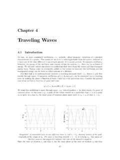
2 Propagation OF Cylindrical WavesIf a wave is emitted from a line source, the wavefronts arecylindrical. Since the wave expands tofill a cylinder of radiusr0, the wavefront crosses a cylindrical area that grows asArea=2 rh , since energy is conserved, the energy per unit area must decrease asrincreases:EArea=constant=E2 rh Er A20r=constant= amplitude A0 rThe equation for a cylindrical wavefront emerging from (or collapsing into) a line source is:f[x, y, z, t]=A[r]cos[kr t]=A0 rcos [kr t])r=px2+y2>0 = emerging + = col lapsingA0=amplitude atr=0 Cylindrical Waves expanding from a line Spherical WavesThe wavefront emerging from (or collapsing into) a point is spherical. The area the wave must crossincreases asx2+y2+z2=r2(area of sphere is4 r2). Therefore the energy density drops HUYGENS PRINCIPLE55the amplitude of the wave must decrease as1r.
3 The equation for a spherical wave isf[x, y, z, t]=f[r,t]=A[r]cos[kr t]=A0rcos [kr t],wherer>0 = emerging + = col lapsingA0=amplitude atr=0 Note the pattern for the amplitude of plane, cylindrical, and spherical Waves :plane wave= 2-D source (plane)= amplitudeA[r] r 0=1cylindrical wave= 1-D source (line)= A[r] r 12spherical wave= 0-D source (point)= A[r] r 1 Spherical Waves expanding from a point Huygens PrincipleI, 1, 3 The spherical wave is the basic wave for light Propagation using Huygens principle. In 1678,Christiaan Huygens theorized a model for light Propagation that claimed that each point on apropagating wavefront (regardless of shape ) could be assumed to be a source of a new sphericalwave. The sum of these secondary spherical wavelets produced the subsequent wavefronts. Huy-gens principle had the glaring disadvantage that these secondary spherical wavefronts propagated backwards as well as forwards.
4 This problem was later solved by Fresnel and Kirchhoffin the 19thcentury. With that correction, the Huygens model provides a very useful model for light propagationthat naturally leads to expressions for diffracted Electromagnetic Waves at a Interface between MediaWe can easily observe that a light wave incident on an interface between two media creates twoother Waves : the refracted and reflected wave. The equations that determine the equations for thesethree electromagnetic Waves are not difficult to derive, though the process is perhaps tedious. Theequations determine the properties of light on either side of the interface, including:1. Equal angles of incidence and reflection;2. Snell s Law that relates the incident and refracted wave;3. Relative intensities of the three Waves ;56 CHAPTER 7. Propagation OF WAVES4. States of polarization of the three Waves ; and5.
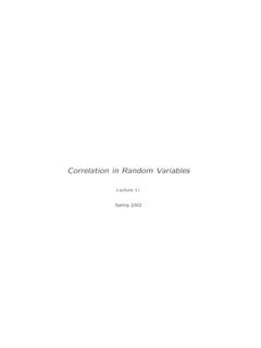
5 Phases of the three light mathematics are based on Maxwell s equations for the three Waves and the continuity con-ditions that must be satisfied at the boundary. For simplicity, we consider only plane Waves , so thateach light wave is described by a single wavevectorkthat points in the direction of Propagation . Theinterface is located atz=0and the incident wavevectork0,thereflected vectorkr, the transmittedvectorktand the unit vector nnormal to the interface are shown:n^ t 0 rk0krktn = n1n = n2xzThekvectors of the incident, reflected, and transmitted (refracted) wave at the interface betweentwo media of drawn, the normal to the surface is the vector with components: n= 001 The incident electricfield is:Eincident=E0ei(k0 r t)Ereflected=Erei(kr r t+ r)Etransmitted=Etei(kt r t+ t)wherer=[x, y, z]is the position vector and rand tare the (perhaps different) initial phases ofthe light Waves .
6 The magnitudes of the wave vectors in the two media differ because the wavelengthis scaled:|k0|= v1=2 1=2 n1 0|kr|= v1=2 1=2 n1 0=|k0||kt|= v2=2 2=2 n2 0where 0is the wavelength in Waves must all have the same phase at the interface located atz=0:(k0 r t)|z=0=(kr r t+ r)|z=0=(kt r t+ t)|z= REFRACTION57which immediately implies that the temporal frequencies of the three Waves must be identical the color of the light does not change as the light travels into a different medium. Therefore thespatial vectors must satisfy the conditions:(k0 r)|z=0=(kr r+ r)|z=0=(kt r+ t)|z=0 Since the scalar product of the three wavevectors with the same vector must be equal, then the threevectors must lie in the same difference of a pair of terms must vanish, which requires that:((k0 kr) r)|z=0= r((k0 kt) r)|z=0= tSince the scalar products of the differences of the wavevectors and the position vectorrare constants,this implies that the position vectors that satisfy these conditions lie in a plane perpendicular to thedifferences of the wavevectors.
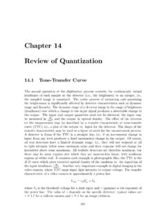
7 The pairs of wavevectors must lie in the same plane perpendicularto the interface, which ensures that: n (k0 kr)= n k0 n kr=0=| n||k0|sin [ 0] | n||kr|sin [ r]=|k0|sin [ 0] |kr|sin [ r]=2 n1 0sin [ 0] 2 n1 0sin [ r]= sin [ 0]=sin[ r]= 0= rBy following the same argument for the second example, we obtain Snell s law for refraction: n (k0 kt)= n k0 n kt=0=| n||k0|sin [ 0] | n||kt|sin [ t]=2 n1 0sin [ 0] 2 n2 0sin [ t]= n1sin [ 0]=n2sin [ r] RefractionWe have already stated that the index of refractionnrelates the phase velocity of light in vacuumwith that in matter:n=cv a dispersive medium, the indexndecreases with increasing , which ensures that thephasevelocity k(of the average wave) is larger than thegroup velocityd dk(of the modulation wave).Refraction is the result of the interaction of light with atoms in the medium and depends onwavelength because the refractive index is also; recall that the index decreases with increasingwavelength:58 CHAPTER 7.
8 Propagation OF Waves n = = C [nm]Fraunhofer DesignationBlueGreenRedTypical dispersion curve for glass showing the decrease in n with increasing and the three spectralwavelengths used to specify refractivity , mean dispersion , and partial dispersion .To afirst approximation, the index of refraction varies as 1, which allows us to write anempirical expression for therefractivityof the mediumn 1:n[ ] 1'a+b whereaandbare parameters determined from measurements. The observation that the indexincreases with demonstrates that the parameterb>0. Cauchy came up with an empirical relationfor the refractivity more free parameters:n 1'A 1+B 2+C 4+ Again, the behavior of normal dispersion ensures thatAandBare both positive. Yet a betterformula was proposed by Hartmann:n'n0+ ( 0) refractive properites of the glass are approximately specified by the refractivity and the measureddifferences in refractive index at the three Fraunhofer wavelengthsF, D,andC:RefractivitynD nD DispersionnF nC>0differences between blue and red indicesPartial DispersionnD nC>0differences between yellow and red indicesAbb Number nD 1nF nCratio of refractivity and mean dispersion,25 65 Glasses are specified by six-digit numbersabcdef,wherenD= ,tothreedecimalplaces,and = Note that larger values of the refractivity mean that the refractive index is larger andthus so is the deviation angle in Snell s law.
9 A larger Abb number means that the mean dispersionis smaller and thus there will be a smaller difference in the angles of refraction. Such glasses withlarger Abb numbers and smaller indices and less dispersion arecrownglasses, while glasses withsmaller Abb numbers areflintglasses, which are denser . Examples of glass specifications includeBorosilicate crown glass (BSC), which has a specification number of 517645, so its refractive indexin the D line its Abb number is The specification number for a commonflintglass is 619364, sonD= (relatively large) and = (smallish). Now consider the refractiveindices in the three lines for two different REFRACTION59 Line [nm]nfor Crownnfor the crown glass:refractivitynD 1= = ' number =516640Fo r th eflint glass:refractivitynD 1= = ' number= Optical Path LengthBecause the phase velocity of light in a medium is less than that in vacuum, light takes longer totravel through a given thickness of material than through the same thickness of vacuum.
10 For afixed distanced, we know that:d=v t(distance=velocity time)=ct1(in vacuum)=cnt2(in medium of index n)= t1=t2n= t2>t1In the timet2required for light to travel the distancedin a material of indexn, light would travela longer distancend=ct2in vacuum. The distancendtraveled in vacuum in the equivalent time istheoptical path lengthin the Reflection and Transmission CoefficientsAs already discussed, radiation is both reflected and refracted at an interface. The relative amounts reflected and refracted are determined by the reflection and transmission coefficients andt,whichare derived by solving Maxwell s equations at the interface to ensure continuity of the electric andmagneticfields. Theamplitude reflection coefficientis defined as the ratio of the amplitude of thereflected electricfield to the incidentfield:ER= E0= =ERE0 Ifthewaveisnormally incidenton the interface, the reflection coefficient is shown to be: =n1 n2n1+n2 Example:If the input medium has a smaller refractive indexn(ararermedium) than the second (denser)medium, then the amplitude reflection coefficient is:60 CHAPTER 7.