Transcription of Protecting semiconductors with high speed fuses
1 Protecting semiconductors with high speed fusesApplication Guide 10507 Effective June 2016 ContentsA: Introduction 3 About this guide 3 Background 3 Typical fuse construction 3 Fuse operation 4 Power semiconductors 4B: high speed fuse characteristics 5 How high speed fuses are different 5 Application factors 5 Influencing factors 6C: Fuse performance data 7 The time-current curve 7 The A-A curve 8 Clearing integral information (factors K and X) 8 The I t curve 8 Peak let-through curve 8 The arc voltage curve 9 Watt loss correction curve 9 Temperature conditions 9D: Determining fuse voltage ratings 9 voltage ratings 9 IEC voltage rating 9 North American voltage rating 9 Simple rated voltage determination 9 Frequency dependency 9 Possible AC/ DC combinations 10AC fuses in DC circuits 10 fuses under oscillating DC 10 fuses in series 10E: Determining fuse amp ratings 11 Part 1 Basic selection 11 Part 2 Influence of overloads 12 Part 3 Cyclic loading and safety margins 13F: high speed fuse applications 14 RMS currents in common bridge arrangements 14 Typical rectifier circuits 15G: Fuse protection for rectifiers 16 Internal and external faults 16 Protection from internal faults 16 Protection from external faults 16 Service interruption upon device failure 17 Continued service upon device failure 17H: fuses protection in DC systems 17DC fed systems 17 Battery as a load 17 Battery as only source 18I: AC fuses in DC circuit applications 18 Calculation example 19J: fuses Protecting regenerative drives 20 Conclusion on the rectifier mode 20 Conclusion on the regenerative mode 21 Summary of voltage selection for regenerative drives 21K.
2 fuses Protecting inverters 22 voltage selection 22 Current selection 22I t selection 22 IGBT as switching device 22 Protection of drive circuits 23 Bipolar power transistors and Darlington pair transistors 23L: Worked examples 23 Example 1: DC Thyristor drive 23 Example 2: high power/ high current DC supply with redundant diodes 24 Example 3: regenerative drive application 25 Appendix 1: International standards 26In the United States 26In Europe 26 Bussmann series product range 26US style North American blade and flush-end 26 European standard 27 Blade type fuses 27 Flush-end contact type 27 British Standard (BS88) 27 Cylindrical/ferrule fuses 27 Appendix 2: Fuse reference systems 28 European high speed fuses 28BS88 high speed fuses 29US high speed fuses 30 Special fuses - Types SF and XL 31 Appendix 3: Installation, service, maintenance, environmental and storage 32 Tightening torque and contact pressure 32 Flush end contact fuses 32 Special flush-end types 32 fuses with contact knives 32 DIN 43653 bolted tag fuses on busbars 32 DIN 43653 bolted tag fuses in blocks 32 DIN 43620 bladed fuses in blocks 32 Press Pack fuses 33 Mounting alignment 33 Surface material 33 Tin-plated contacts 33 Vibration and shock resistance 33 Service and maintenance 33 Environmental issues 33 Storage 33 Glossary 34-35 Contact information Back coverBussmann series high speed fuse portfolioThese high speed fuse styles are available in the voltages and ampacities indicated.
3 For details, see Bussmann series high speed fuse catalog no. 10506 or full line catalog no. high speed fuses 500 Vac/dc, 50 to 400 AFerrule fuses Up to 2000 Vac/1000 Vdc, 5 to 100 ABritish Standard BS 88 Up to 700 Vac/500 Vdc, 6 to 710 ADFJ UL Class J drive fuse Full range, 600 Vac/450 Vdc, 1 to 600 ASquare body fuses Up to 1300 Vac/700 Vdc, 10 to 5500 ANorth American fuses Up to 1000 Vac/ 800 Vdc, 1 to 4000 AIGBT fuses Up to 1000 Vdc, 25 to 630 : IntroductionAbout this guideThis guide s objective is to provide engineers easy access to Bussmann series high speed fuse data. It also provides detailed information on the Bussmann series high speed fuse reference system. The various physical standards are covered with examples of applications along with the considerations for selecting rated voltage , rated current and similar data for Protecting power semiconductors . Guidelines for fuse mounting is covered, with explanations on how to read and understand product data sheets and document is not a complete guide for Protecting all power semiconductor applications.
4 The market is simply too complex to make such a document, and, in some cases, the actual fuse selection will require detailed technical discussions between the design engineers specifying the equipment and Application Engineering , the data presented here will be of help in daily work and provide the reader with the basic knowledge of our products and their fuse has been around since the earliest days of the telegraph and later for Protecting power distribution and other fuse has undergone considerable evolution since those early days. The modern high Breaking Capacity (HBC)/ high interrupting rating fuse provides economical and reliable protection against overload and fault currents in modern electrical fuse operation is simple: excess current passes through specially designed fuse elements causing them to melt and open, thus isolating the overloaded or faulted circuit. fuses now exist for many applications with current ratings of only a few milliamps to many thousands of amps, and for use in circuits of a few volts to 72 kV utility distribution most common use for fuses is in electrical distribution systems where they are placed throughout the system to protect cables, transformers, switches, control gear and equipment.
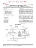
5 Along with different current and voltage ratings, fuse operating characteristics are varied to meet specific application areas and unique protection definitions on how fuses are designed for a certain purpose (fuse class) are included in the fuse constructionModern high speed fuses are made in many shapes and sizes (Figure A1), but all have the same key features. Although all fuse components influence the total fuse operation and performance characteristics, the key part is the fuse element. This is made from a high conductivity material and is designed with a number of reduced sections commonly referred to as necks or weak spots. It is these reduced sections that will mainly control the fuse s operating element is surrounded with an arc-quenching material, usually graded quartz, that quenches the arc that forms when the reduced sections melt and burn back to open the circuit. It is this function that gives the fuse its current-limiting contain the quartz arc-quenching material, an insulated container (commonly called the fuse body) is made of ceramic or engineered plastic.
6 Finally, to connect the fuse element to the circuit it protects there are end connectors, usually made of copper. The other fuse components vary depending on the type of fuse and the manufacturing methods end capCeramic bodyEnd connectorOuter end capElementEnd connectorEngineered plastic and glass fiber bodyElementEnd plateCeramic bodyElementEnd fittingScrewElement reduced sections or necks / weak spots Figure A1. Typical square body and round body high speed fuse operationFuse operation depends primarily on the balance between the rate of heat generated within the element and the rate of heat dissipated to external connections and surrounding atmosphere. For current values up to the fuse s continuous current rating, its design ensures that all the heat generated is dissipated without exceeding the pre-set maximum temperatures of the element or other conditions of sustained overloads, the rate of heat generated is greater than that dissipated, causing the fuse element temperature to rise.
7 The temperature rise at the reduced sections of the elements ( necks or weak spots ) will be higher than elsewhere, and once the temperature reaches the element material melting point it will start arcing and burn back until the circuit is opened. The time it takes for the element to melt and open decreases with increasing current current level that causes the fuse to operate in a time of four hours is called the continuous current rating, and the ratio of minimum fusing current to the rated current is called the fusing factor of that fuse. Under higher overloading, or short-circuit conditions, there is little time for heat dissipation from the element, and the temperature at the element s reduced sections (necks) reach the melting point almost instantaneously. Under these conditions, the element will commence melting well before the prospective fault current (AC) has reached its first major time taken from the initiation of the short-circuit to the element melting is called the pre-arcing time.
8 This interruption of a higher current results in an arc being formed at each reduced section with the arc offering a higher resistance. The heat of the arcs vaporize the element material; the vapor combines with the quartz filler material to form a non-conductive, rock-like substance called fulgurite. The arcs also burn the element away from the reduced sections to increase the arc length and further increase the arc resistance. The cumulative effect is that the arcs are extinguished in a very short time along with the complete isolation of the circuit. Under such heavy overload and short-circuit conditions the total time taken from initiation of fault to the final isolation of the circuit is very short, typically in a few milliseconds. Therefore, current through the fuse has been limited. Such current limitation is obtained at current levels as low as four (4) times the normal continuous current rating of the time taken from the initiation of the arcs to their being extinguished is called the arcing time.
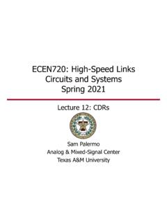
9 The sum of the pre-arcing and arcing time is the total clearing time (see Figure A2). During the pre-arcing and the arcing times a certain amount of energy will be released depending on the magnitude of the current. The terms pre-arcing energy and arcing energy are similarly used to correspond to the times. Such energy will be proportional to the integral of the square of the current multiplied by the time the current flows, and often abbreviated as I2t, where I is the RMS value of the prospective current and t is the time in seconds for which the current high current values, the pre-arcing time is too short for heat to be lost from the reduced section (is adiabatic) and pre-arcing I2t is therefore a constant. The arcing I2t, however, also depends on circuit conditions. The published data is based on the worst possible conditions and is measured from actual tests. These will be covered in detail arcing causes a voltage across the fuse element reduced sections (necks) and is termed the arc voltage .
10 Although this depends on the element design, it is also governed by circuit conditions. This arc voltage will exceed the system voltage . The design of the element allows the magnitude of the arc voltage to be controlled to known limits. The use of a number of reduced sections (necks) in the element, in series, assists in controlling the arcing process and also the resulting arc , a well-designed fuse not only limits the peak fault current level, but also ensures the fault is cleared in an extremely short time and the energy reaching the protected equipment is considerably smaller than what s semiconductorsSilicon-based power semiconductor devices (diodes, thyristors, Gate Turn-Off thyristors [GTOs], transistors and Insulated Gate Bipolar Pre-arcing timePossible, unrestricted fault currentPeak fault current reached at start of arcingStart of faultActual currentArcing timeTotal clearing timeTA: IntroductionFigure A2. Pre-arcing time plus arcing time equals total clearing [IGBTs]) have found an increasing number of applications in power and control circuit rectification, inversion and regulation.