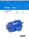
Transcription of PVE Piston Pumps - Vickers
1 Piston PumpsPVE12 variable displacement Single PumpPVE19 / PVE21 variable displacement Single & Thru-Drive PumpsPVE4* 25V Integrated ModelsGB C 2023 Vickers Piston of .. Operating .. PVE12 Model .. Shaft Torque .. Performance .. Installation .. Shaft .. Adjustable Maximum Volume StopLoading Sensing with Pressure LimiterRemote Adjustment CompensatorPVE19 / 21 Model .. Shaft Torque .. Typical Rear Pumps for PVE19 / 21 .. Performance .. Installation .. Side Ports and C-type ControlEnd Ports and C-type .. Adjustable Maximum Volume StopLoading Sensing with Pressure LimiterRemote Adjustment CompensatorShaft .. Thru-DrivePVE19/21 * TA9/11 SAE .. PVE19/21 * TB26 SAE .. PVE4*-25 VModel .. Shaft Torque .. Performance .. Installation .. CompensatorRemote Adjustment CompensatorShaft .. Application Data .. PVE Piston Pumps are inline, variable displacement Pumps that areavailable in three displacement assortment of optional controls offermaximum operating flexibility.
2 Pumpdisplacement is varied by means ofpressure and/or flow Integrated PumpA unique integrated pump package isalso available. This package includes a72 or 79 l/min (19 or 21 USgpm at 1800r/min) PVE Piston pump and a 25V fixedintra-vane pump in a single inlet, doubleoutlet ported unit. This compact packageis used in a wide variety of circuits withboth fixed and variable flowrequirements. The result is lowerinstalled costs as only one mounting padand one inlet line are needed for the twoindependent and Benefits Inline, variable displacement pump Three displacement sizes displacement is varied bypressure/flow compensator controls Optional controls for maximumoperating flexibility Thru-drive available on PVE 19/21 Unique integrated pump package alsoavailable25V outletPVE outletControlPVE12 PVE19/21 PVE41/45-25 VIntegrated PumpPVE41/45 Piston pump section25V intra-vane CompensatorControl, C OptionThis control automatically varies pumpdisplacement to meet the system flowdemand for a constant system starts to reduce to zerowithin 14 bar (200 psi) of thecompensator setting.
3 Power draw-off isminimized, therefore, system reliefvalves should not be CompensatorControl with MaximumDisplacement Adjustment, CC OptionAs indicated for C option above,except there is an independent screwadjustment of maximum displacementfrom 100% (rated) to 25%. CC Note: Graphic symbols shown withexternal valve(s) and cylinder toillustrate typical Sensing Compensatorand Pressure Limiter, CVP(C) OptionThis compensator provides load sensingcontrol under all pressure conditions upto the desired maximum. It automaticallyadjusts pump flow in response to aremote pressure signal and maintainsoutlet pressure at approximately 11 bar(160 psi) above load pressure. Theintegral pressure limiter overrides theload sensing control, reducing pumpdisplacement as the preset maximumoperating pressure is reached. Overridebegins within 14 bar (200 psi) of thepreset maximum pressure compensatorsetting.
4 CVP(C) Note: Optional internal bleed orificediameter is .015 PVE with PressureCompensator Arranged forRemote Control, CG OptionExactly the same as the C (pressurecompensation option) except themachine operator is able to change thecompensator setting through the use ofa remote pilot relief valve. CG NOTEA kit is available for an electrical dualpressure compensator. This controlautomatically adjusts pump deliveryto maintain system volumerequirements at either of twopreselected operating pressuresThis allows lower settings for lowhorsepower start-up, equipmenttesting, etc. This kit also allows forhigher pressure settings as requiredin machine applications. For detailsrefer to service drawing I 3255 DataDisplacement, Speed, andPressure RatingsDisplacement cm3/r (in3/r)Rated InputMaximum Pressure bar (psi)Model CodeShaft End PumpCover End PumpSpeed (At 0 psig Inlet)Shaft EndCover EndPVE1225 ( ) 3000207 (3000) PVE1941 ( ) 2400207 (3000) PVE2145 ( ) 2400186 (2700) PVE41-25V40M (mobile)41 ( )40 ( )2400207 (3000)207 (3000)PVE41-25V45M (mobile)41 ( )45 ( )2400207 (3000)207 (3000)PVE41-25V55M (mobile)41 ( )55 ( )2400207 (3000)207 (3000)PVE41-25V67M (mobile)41 ( )67 ( )2400207 (3000)207 (3000)PVE45-25V40M (mobile)45 ( )40 ( )2400186 (2700)207 (3000)PVE45-25V45M (mobile)45 ( )45 ( )2400186 (2700)207 (3000)PVE45-25V55M (mobile)45 ( )55 ( )2400186 (2700)207 (3000)PVE45-25V67M (mobile)45 ( )67 ( )2400186 (2700)207 (3000)PVE41-25V40I (quieted)41 ( )40 ( )1800207 (3000)172 (2500)PVE41-25V45I (quieted)41 ( )45 ( )1800207 (3000)172 (2500)
5 PVE41-25V55I (quieted)41 ( )55 ( )1800207 (3000)172 (2500)PVE41-25V67I (quieted)41 ( )67 ( )1800207 (3000)172 (2500)Pressure Limits*PortPressure RangeInlet 0,2 bar to 2,0 bar (5 in. Hg. vacuum to 30 psi)OutletSee Maximum Pressures listed aboveDrain0,35 bar (5 psig) maximum* Integral relief valve protects pump by limiting case pressure peaks to 0,7 bar (10 psi) aboveinlet pressure. Flow from valve returned directly to pump inlet. Case drain line required tolimit steady-state case pressure. See page for Inlet vs. Speed for Start-upBefore starting a PVE pump, fill the casethrough the uppermost drain port withsystem hydraulic fluid. The case drainline must be connected to the reservoirbelow oil level. For multiple pumparrangements that include non-PVEsections, the requirements of thenon-PVE units must also be Engineering recommends thesePVE series Piston Pumps be Limits At Full Flow ConditionsDisplacement cm3/r (in3/r)InletPressure/Vacuum*Maximum Speed**rpm5 psig2800 PVE21 full displacement 45 ( )0 psig2400 PVE19 full displacement 41 ( )5 in.
6 Psig3100 PVE19/21 destroked 33 ( )0 psig2750 PVE19/21 destroked 33 ( )5 in. psig3200 PVE19/21 destroked 25 ( )0 psig3000 PVE19/21 destroked 25 ( )5 in. limited to 3000 rpm at full displacement and 0 psig inlet.* Minimum pressure/vacuum required at pump inlet to operate at displacement and speed listed.** Speeds not listed, but within displacements shown above, may be calculated from values Load Sense Standby Condition CVP(C) ControlsPump must be in zero flow, low pressure, standby condition when operated at listedspeed. Pump may be damaged if not slowed to normal rated speed before beingoperated at full CodeMaximum SpeedrpmPVE123600 PVE193200 PVE213200 Response DataYoke response recorded at rated speed and pressure, 0 psi inlet, 82 C (180 F), SAE 10W oil. Pressure rise was 6900 bar(100,000 psi) per TypeOn Stroke Stroke Stroke Stroke sense DataSound level dB(A) per ISO 4412 rpm, 70 bar (1000 psi)1500 rpm, 140 bar (2000 psi)1800 rpm, 207 bar (3000 psi)Model CodeFull StrokedB(A)CompensatedStroke dB(A)Full StrokedB(A)CompensatedStroke dB(A)Full StrokedB(A)CompensatedStroke dB(A) Code1 Model seriesPVE Piston pump, variable , E series2 Frame size12 45 l/min (12 USgpm) @ 1800 rpm25cm3/r ( in3/r)3 Rotation (viewed from shaft end)R Right handL Left hand4 Mounting flangeB SAE B 2-bolt5 Input shaft1 SAE B straight keyed2 SAE B splined28 26 tooth splined (special Vickers ).
7 See chart below6 Port configurationE End ported, SAE O-ring ports(standard)M End ported, metric O-ring ports perISO 6149 (optional)7 Shaft sealS Single8 Pump design10 10 seriesSubject to change. Installationdimensions remain the same for designnumbers *0 to *9 Adjustable maximum volume stopC With stop optionBlank Omit if not required10 Control optionsC** Pressure compensator,adjustable from 20 207bar (300 3000 psi).Standard setting C21 indicates 207 bar (3000psi). (standard)CG Remote adjustmentpressure compensator(optional)C**VP11 Load sensing with C typepressure limiter. Loadsense set at 11 bar (160psi). (standard)C**VPC24 Load sense with C typepressure limiter. Loadsense set at 24 bar (350psi). (optional)** indicates pressure compensatorsetting in tens of Control bleed down(CVP models only)B Bleed down orifice ( dia.)in load sense control(standard)P Plug, no bleed down orifice inload sense control (optional)Blank Omit for C, CC, CD and CGmodels12 Control design11 CC, CG, and CCG12 CVP, CVPC, CCVP, and CCVPC13 Special suffixBlank Omit if not required298 Special CG control for use withelectronically modulated relief valvePVE12 Shaft Torque DataInput ShaftDesignationThru Drive OptionMaximum Input Torque ( )1 SAE B straight keyedNo135 (1200)2 SAE B spline 13T, 16/32 , FRMDFNo208 (1850)28 Special Vickers 26T for use in rear pump oftandem PVE**-PVE12 CurvesPVE12 Oil type: SAE 10 WOil temperature: 82 C (180 F)Inlet pressure.
8 0 psi1149576573819051015202530500100015002 00025003000 Speed rpmEffective Flow Versus SpeedInput Power Versus SpeedOverall Efficiency Versus SpeedInput power kWDelivery l/minDelivery rpmInput Power kWInput Power hp01008060402050010001500200025003000 Speed rpmOverall Efficiency %035 bar (500 psi)207 bar (3000 psi)207 bar (3000 psi)140 bar (2000 psi)70 bar (1000 psi)35 bar (500 psi)207 bar (3000 psi)140 bar (2000 psi)70 bar (1000 psi)35 bar (500 psi) Dimensions27,0( )Alternate drain port D1 .750 - 16 UNF - 2B O Ring boss connection .500 tubing29,5 ( )85,1( )170,2( )153,5( )Construction plugsDo not remove51,5( )70,0( )73,0( )30,0( )19,5 R( R) 120,6( )14,0 R( R)2 places14,5314,15( )( ) rotation25,0( )146,0( )140,0( ) 101,60 101,55( )( )14,0 ( ) 9,4( )0,76( )max. R167,5 ( )196,6 ( )162,5 ( )186,1 ( )47,0( )44,0( )44,0( ) 28,4( ) 56,0( )2 placesCompensatorposition (reversefor rotation)Drain port D2.
9 750-16 UNF-2B port (seenote) thd. SAEO-ring bossconnection . tubing (shownfor rotation)Inlet port(see note) ,0( )83,1( )77,0( )154,0 ( )114,1( )79,2( )52,0( )70,0( )25,1224,87( )( ) 22,225 22,200( )( )6,3756,350( )( )long key31,75( ) ( )x 45 ( )58,6( )No. 1 Shaft: SAE B Straight KeyedPVE12 Shaft Options5,5( )SAE B modified involute spline( major diameter, minimum minor diameter).Flat root, side fit. Class 5 perANSI 1976. 13 teeth,16/32 diameter pitch,30 pressure ,5( ) ( )30 x 45 19,0( )41,1( )33,3( )No. 2 Shaft: SAE B SplinedNOTEA pplications requiring overhung load or side loadingof shaft are subject to Vickers engineering are reversedfor with C-type ControlsPVE12 CC AdjustableMaximum Volume StopSee installation dimensions page other the locknut on the adjusting the adjusting rod clockwise todecrease maximum pump delivery, orcounterclockwise to increase maximumpump delivery, until the desired setting isobtained.
10 Secure the setting bytightening the locknut. To assist initialpriming, the manual adjustment controlsetting must be at least 40% of themaximum flow control enables maximum pumpdelivery to be externally adjusted from25% to 100% while maintaining all thestandard features of a pressurecompensated CVP Load Sensingwith Pressure Limiter52,0( )72,6( )90,1( )63,8( ) 28,4( )123,8( )30,0( )250,1( )218,2( )194,2( )11,8( ) stopadjusting rod(Approx. 2,22 cc/revchange per turn)Compensator positionfor rotationCompensator positionfor rotation214,3( ) 28,4( )19,0( )52,0( )128,3( )70,6( )191,0( )Load sensingcompensatorcontrol port locationfor rotationCompensatorposition rotationLoad sensing compensator controlport location for UNF-2B thd. SAE O-ringboss connection .250 tubing68,3( )10,6( )Compensatorposition rotationLocknut11,2( )across CG RemoteAdjustment CompensatorSee installation dimensions page other ,0( )20,9( )114,8( )75,1( )15,1( )54,8( )54,8( )Compensator control portlocation for UNF-2B thd.