Transcription of Quick Reference Install Guide
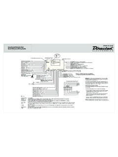
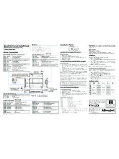
1 2015 Directed. All rights Reference Install GuideVehicle Security SystemModels 3105 and 3305 Guide TranslationsFor a French version of the Installation Guide , please download it from under Resources .Traduction du Guide :Pour une version fran aise du Guide d installation, veuillez le t l charger sous Resources .Sensor adjustment detailOptional Sensor PortWhite 4 Pin PlugLED PortWhite 2 Pin PlugVatet Switch PortBlue 2 Pin PlugAntennaPort(-)(+)Red/White (-) 200mA Chan 2 OutputGreen (-) Lock, (+) Unlock OutputBlue (-) Unlock, (+) Lock OutputLight Flash JumperRed (+) 12V Constant PowerBrown (+) Siren/Horn OutputYellow (+) Ignition InputBlack (-) Chassis GroundViolet (+) Door Trigger InputBlue (-) Instant Trigger InputGreen (-) Door Trigger InputBlack/White (-) Domelight Sprvsn OutputWhite/Blue (-) 200mA Chan 3 OutputWhite (+/-) Light Flash OutputOrange (-)
2 500mA GWA OutputProgramming Port: The 998T Bit-writer can be connected to this port for programming feature options. SmartStart can be connected to this port to operate the system by the shock sensor pot: 1. Securely mount the CPU (in a safe location) before adjusting 2. Turn the sensor adjustment clockwise to increase sensitiv-ity, turn counterclockwise to decrease sensitivity(-) Lock, (+) Unlock Output: Con-nect to a wire that pulses ground to activate the vehicle lock relay or to a wire that pulses (+) 12V to acti-vate the vehicle unlock relay(-) Unlock, (+) Lock Output: Con-nect to a wire that pulses (-) ground to activate the vehicle unlock relay or to a wire that pulses (+) 12V to activate the vehicle lock relayWiring ConnectionsChannel 2 Output.
3 Connect to the vehicle negative (-) trunk release re-lay or other low current Constant Power: Remove the inline fuse before connecting to a wire that has (+) 12V at all Output: Connect to the (+) wire on the siren or Input: Connect to a wire that has (+) 12V while the key is in the run and crank Ground: Connect to a scraped (bare) metal surface in the driver Trigger Input: Connect to a wrie that goes to (+) 12V when any door is Trigger Input: Connect to a wire that goes to ground (-) when the hood or trunk are Trigger Input: Connect to a wire that goes to (-) ground when any door is Supervision Output: Connect to a (-) wire that will turn on the 3 Output: Connect to an auxiliary relay or low current Flash Output: Connect to the vehicle parking light wire.
4 This wire is programmable + or When Armed Output: Connect to a starter interrupt relay or other accessory that requires a : NEVER connect 200mA low current outputs directly to a motor or high current device WITHOUT a relay,Bitwriters with a date code of 6a or older require an IC upgrade (p/n 998M). Some bitwriters with a date code of 6B do not require the IC upgrade, refer to tech tip # 1112 for more information. The Bitwriter (p/n 998U) requires chip version or newer to program this control configuration4- button remote control configurationFeatureDescriptionA U XArm: Lock the doors and arm the vehicleA U XDisarm: Unlock the doors and disarm the vehicleAUXC hannel 2/Silent Mode: Activate Silent Mode and Auxiliary functionsAUXP anicA U X and A U XChannel 3: Press together to control an Auxiliary outputMore information and full Installa-tion Guide can be found online at: 2015 Directed.
5 All rights 2015 -08 Programming System FeaturesThe System Features Learn Routine dictates how the unit operates. It is possible to ac-cess and change most of the feature settings using the Valet switch/Control button.**Depending on which model is installed, the system uses either an external Valet switch and an external Status LED or a Control Center with an onboard Control but-ton (Valet Switch) and Status Open a door. 2. Tu r n the ignition on, then off. 3. Select a Menu. Press and hold the Valet switch/Control button. The number of siren chirps indicates the menu number.
6 1 chirp indicates menu 1, 2 chirps - menu When the desired menu chirps are heard, release the Valet switch/Control Select a Feature. Press and release the Valet switch/Control button the number of times corresponding to the feature you wish to change. Then press and hold one more time to select the Program the Feature. While holding the Valet switch/Control button, you can program the feature using the remote control. To change the desired options press; AUX = one chirp setting, while AUX = two chirps setting. Once a feature is programmed: Other features can be programmed within the same menu Another menu can be selected The learn routine can be exited if programming is completeTo access another feature in the same menu:1.
7 Press and release the Valet switch/Control button the number of times neces-sary to advance from the feature you just programmed to the next one you want to Then press the Valet switch/Control button once more and hold it. To select another menu:1. Press and hold the Valet switch/Control After 3 seconds, the unit advances to the next menu and the siren chirps, indi-cating which menu has been learn routine exits if any of the following occurs: The open door is closed The ignition is turned On There is no activity for 20 seconds The Valet switch/Control button is pressed too many timesBitwriter - Only OptionsIf programming with the Bitwriter , the learn routine can be locked or un-locked.
8 If the learn routine has previously been locked, it must be unlocked with Bitwriter - this cannot be done manually with the Control Bitwriter gives you access to a wider range of system options. These features and the adjustments that may be programmed are described in the table below. Default settings are in bold type. Menu ItemFeatureDefaultOption 21 Ignition Controlled LockIgnition Controlled Lock ONIgnition Controlled Lock OFF2 Ignition Controlled UnlockIgnition Controlled Unlock ONIgnition Controlled Unlock OFF3 Siren Duration30 second siren duration1-180 seconds (in 1 second increments)Feature MenusDefault factory settings are in bold type.
9 Menu 1: Basic FeaturesFeature # 1- chirp setting2- chirp setting1-1 Active arming Passive arming1-2 Chirps ONChirps OFF1-3 Ignition controlled door locks ONIgnition controlled door locks OFF1-4 Active locking onlyPassive locking1-5 Panic w/ignition ONNo Panic w/ignition second door lock second door lock pulses1-7 Forced passive arming ONForced passive arming OFF1-8 Automatic Engine Disable ONAutomatic Engine Disable OFF 1-9 Armed When Driving (AWD) Vehicle Recovery System (VRS) 1-10 Code Hopping ONCode Hopping OFFMenu 2: Advanced FeaturesFeature # 1- chirp setting2- chirp setting2-1 Siren* Horn Honk*2-230 second siren duration60 second siren duration2-3 NPC ONNPC OFF2-4 Progressive door triggerInstant door trigger2-5 Valet switch/Control button input: 1 pulseValet switch/Control button input 2-5 pulses2-6 Door trigger error chirp ONDoor trigger error chirp OFF2-7 Ignition controlled domelight ONIgnition controlled domelight OFF2-8 Single unlock pulseDouble unlock pulse 2-9 Single lock pulse Double lock pulse 2-10 Channel 3: ValidityChannel 3.
10 Latched/ latched reset with ignition/30- second timed/second unlock output**2-11 Comfort Closure (ON, 20 sec) Comfort Closure (OFF) * In Horn Honk setting the brown wire (12-pin) outputs pulses. In Siren setting the wire outputs continuously. This wire has a (+) polarity output regardless of setting.** Second unlock available only if feature 2-8 is programmed to single control learn routineThe system comes with two remote controls that have been taught to the control module. The control module can store up to four different remote control codes in memory.