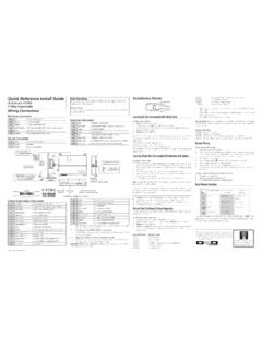
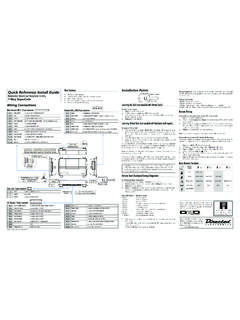
Transcription of Quick Reference Install Guide Installation Points
1 2016 Directed. All rights Reference Install GuideRemote Start with Keyless Entry 4X05 series 4115 1-button and 4105 4-button systemsValet ButtonDoor Lock/unlockHarnessEnd ViewAntennaAntennaLED (Programmingindicator)Parking light jumpersPrimary HarnessRemote Start HarnessHeavyGaugeRelayEnd ViewSide ViewSide ViewTop ViewSatellite HarnessD2 DBitwriter/SmartstartWiring ConnectionsPrimary Harness, White 9-pin connector1 LIGHT GREEN BLACK(-) 200mA FACTORY ALARM DISARM OUTPUT2 GREEN/WHITE(-) 200mA FACTORY ALARM REARM OUTPUT3 YELLOW(+) IGNITION OUT (TO ALARM) 4 WHITE/BLUE(-) ACTIVATION INPUT 5 ORANGE(-) 500mA GROUND WHEN LOCKED/ANTI-GRIND OUTPUT6 BROWN(-) 200mA HORN OUTPUT7 RED/WHITE(-) 200mA TRUNK RELEASE OUTPUT*8 BLACK(-) CHASSIS GROUND9 WHITE(+/-) LIGHT FLASH OUTPUT*Option not applicable to 1- button remote controlRemote Start harness, White 5-pin connector1 BLACK/WHITE(-) PARKING BRAKE INPUT*2 VIOLET/WHITETACHOMETER INPUT3 BROWN (+) BRAKE SHUTDOWN INPUT4 GRAY(-) HOOD PIN SWITCH SHUTDOWN INPUT5 BLUE/WHITE(-) 200 mA 2ND STATUS/REAR DEFOGGER OUTPUT* Connect this wire to the (-) Parking Brake wire in the vehicle.
2 The parking brake must be applied for the remote start to to Installer A remote Start Safety Check must be performed before returning the vehicle to the owner. This Safety Checklist document (TB101) can be found online by going to and can also be found in the full online Installation Guide (N4X05). The Valet Button must be installed as it is required for disabling the remote Start System/Garage Mode. Heavy Gauge Relay, White 6-pin connector1 RED(+) (30A) HIGH CURRENT 12V INPUT2 PINK/WHITE(+) SECOND IGNITION/ACCESSORY CIRCUIT OUTPUT3 RED(+) (30A) HIGH CURRENT 12V INPUT 4 ORANGE(+) ACCESSORY OUTPUT5 PURPLE(+) STARTER OUTPUT6 PINK(+) IGNITION 1 INPUT/OUTPUTS atellite harness - White 4-pin connector1 BLUE(-) 200mA STATUS OUTPUT2 ORANGE(-) 200mA ACCESSORY OUTPUT3 PURPLE(-) 200mA STARTER OUTPUT4 PINK(-) 200mA IGNITION OUTPUTDoor Lock, White 3-pin connector1 LIGHT BLUE(-) 200mA UNLOCK OUTPUT2 EMPTYNOT USED3 GREEN (-) 200mA LOCK OUTPUTI mportant.
3 NEVER connect 200mA low current outputs directly to a motor or high current device WITHOUT a Harness, Red 4-pin connector1 BLUED2D - TX2 BLACK(-) GROUND3 GREEND2D - RX4 RED(+) 12 VBitwriter/Directed SmartStart Harness, Black 3-pin connector1 RED(+) 12V2 ORANGEESP2 - RX/TX3 BLACK(-) GROUNDI nstallation PointsLearning Hardwired or Data Tach (not needed with Virtual Tach)To learn the tach signal:1. Start the vehicle with the Within five seconds, press and hold the Valet After three seconds the LED will light constant when the tach signal is Release the Valet button and turn OFF the : This unit can learn the tachometer with the analog input or through D2D using an interface module.
4 The unit confirms which source is used by flashing the parking programming tach learning with: The analog Violet/White Tachometer input, the parking lights flash one time. A D2D interface module, the parking lights flash the analog tachometer input on the system is connected to the vehicle, the D2D tachometer input will be Virtual Tach (not needed w/hardwire and data tach inputs)Note: Virtual Tach is not recommended for diesel program Virtual Tach:1. After the Install is complete, remote start the car. 2. If the car does not start on the first attempt, let the remote start attempt again (three cranks may be required to start and run the engine).
5 3. Once the car starts, let the engine run for 30 Use the remote control to shut OFF the remote start- that s it! Virtual Tach is Tach handles disengaging the starter motor during remote starting it does not address over-rev. If the customer wants to have the over-rev protection capabil-ity, the tach wire must be connected. Important: If the Virtual Tach mode over or under cranks, use the Bitwriter to add or subtract the starter output time. You can adjust the output time in increments of 50 milliseconds. Reset and DeletionIf a feature/Virtual Tach needs to be reset or the remote controls need to be deleted, use the following Tu r n the vehicle ignition to the ON Within five seconds press and release the Valet button: two times to delete remote controls, three times to reset the features to default or four times to reset Virtual Once you have selected the function step, press the Valet button once more and hold it.
6 The LED will flash and the horn (if connected) will honk to confirm the functional step chosen. Do not release the Valet Press the AUX button of a programmed remote control. The horn (if connected) will honk confirming the feature has been Release the Valet button and turn OFF the the ignition. The horn (if connected) honks to confirm : Deleting a remote control does not reset the features or virtual tach, resetting the features does not delete remote controls or reset virtual tach. The Zap feature on the Bitwriter will not reset the virtual tach will exit if: The ignition is turned OFF. There is no activity for 30 seconds.
7 The Valet button is pressed too many times. remote Start Shutdown/Startup DiagnosticsIf the remote start activates but fails to stay running, the remote start module has the ability to inform you of what may have caused the remote start failure. Before performing the shutdown diagnostics it is important that you let the remote start shut off on its own , let it attempt to start three times then shut down, if this is not done and you press on the brake or use the remote , the unit will report the shutdown last used to shut off the remote perform shutdown diagnostics:1. With the ignition OFF, press and hold the Valet Tu r n the ignition ON and then back OFF while holding the Valet Release the Valet Press and release the Valet button.
8 The LED flashes to report the last shutdown for one minute or until the ignition is turned on, as shown in the following table:Status LED Flashes Shutdown Mode1 flash Runtime expired 2 flashes Over-rev shutdown 3 flashes Low or no RPM4 flashes Transmitter shutdown (or optional push button)5 flashes (+) Brake shutdown 6 flashes Hood shutdown8 flashes (-) Parking brake ( remote Start harness BLACK/WHITE wire)9 flashes Low battery (voltage mode)Startup Diagnostics: If the vehicle fails to activate the remote start, the remote start module will notify you via parking light flashes on the vehicle to identify the no-start Light Flashes5 flashes Brake wire is active6 flashes Hood pin wire is active8 flashes (-) Parking brake ( remote Start harness BLACK/WHITE wire) 9 flashes remote Start is disabled by Garage Mode.
9 (see Disabling the remote Start System section for more detail).Disabling the remote Start System/Garage ModeGarage Mode is a safety feature that disables the remote start system if the vehicle is parked in a garage, being serviced, or used by someone unfamiliar with remote start systems. When Garage Mode is ON, any attempt to start the engine, activate Timer Mode, or enter Pit Stop mode is denied and remote start diagnostics flashes the parking lights nine Garage Mode on or off:1. Tu r n the ignition on then Within 10 seconds, press and release the Valet button The LED turns The parking lights flash: Nine times quickly when turning on.
10 Nine times slowly when turning detailed information about this system can be found online at: 2016 Directed. All rights 2016-10 Programming System FeaturesThe System Features Learn Routine dictates how the unit operates. It is possible to access and change most of the feature settings using the Valet button. 1. Tu r n the ignition ON, then OFF. 2. Within five seconds, press and hold the Valet button. The number of LED flashes and horn honks (if con-nected) indicates the menu number. A single LED flash and honk (if connected) indicates Menu 1. Two LED flashes and 2 honks (if connected) indicates Menu 2. 3. When the desired Menu LED flashes and honks (if connected) are heard, release the Valet Within five seconds, press and release the Valet button the number of times corresponding to the feature you want to change.