Transcription of Quick Start Guide - cisco.com
1 Quick Start GuideCisco Small Business200 Series Smart Switches2200 Series Smart SwitchesWelcomeThank you for choosing the cisco 200 Series Smart Switch, a cisco Small Business network communications device. This device is designed to be operational right out-of-the-box as a standard bridge. In the default configuration, it will forward packets between connecting devices after powered up. Before you begin installing the switch, make sure you have all of the package contents available, access to the cisco Small Business 200 Series Smart Switch Administration Guide , and a PC with a web browser for using web-based system management Contents cisco 200 Series Smart Switch.
2 Rackmount Kit. Power Cord or Adapter This Quick Start Guide . Product Guide will familiarize you with the layout of the smart switch and describe how to deploy the device in your network. For additional information, see the cisco SwitchThere are two ways to mount the switch: Set the switch on a flat surface. Mount the switch in a standard rack (1 rack unit high). Do not mount the device in a location where any of the following conditions exist:High Ambient Temperature The ambient temperature must not exceed 104 degrees Fahrenheit (40 degrees Centigrade).
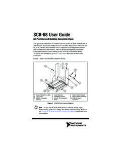
3 NOTESome switches have a higher temperature rating. The SG200-10FP, SF200-24FP, SG200-26FP, and SG200-50FP are rated at 113 degrees Fahrenheit (45 degrees Centigrade).Reduced Air Flow Both side panels must be unobstructed to prevent Series Smart Switches3 Mechanical Overloading The device must be level, stable, and secure to prevent it from sliding or shifting Overloading Adding the device to the power outlet must not overload that PlacementSTEP1 Remove the four screws from each side near the front of the switch.
4 Retain the screws for re-installation. (Do not remove the four screws from each side near the back of the switch.)STEP2 Place one of the supplied spacers on the side of the switch so the four holes of the spacers align to the screw holes. Place a rack mount bracket next to the spacer and reinstall the four screws removed in Step your screws are not long enough to reattach the bracket with the spacer in place, attach the bracket directly to the case without the Step 2 for the other side of the the mounting hardware has been securely attached, the switch is now ready to be installed into a standard 19-inch stability, load the rack from the bottom to the top, with the heaviest devices on the bottom.
5 A top-heavy rack is likely to be unstable and might tip Series Smart SwitchesConnecting Network DevicesTo connect the smart switch to the network:STEP1 Connect the Ethernet cable to the Ethernet port of a computer, printer, network storage, or other network device. STEP2 Connect the other end of the Ethernet cable to one of the numbered smart switch Ethernet ports. The LED of the port lights if the device connected is active. Refer to Features of the cisco Small Business Smart Switch, page 9 for details about the different ports and LEDs on each Step 1 and Step 2 for each device you want to connect to the smart strongly recommends using Cat5 or better cable for Gigabit connectivity.
6 When you connect your network devices, do not exceed the maximum cabling distance of 100 meters (328 feet). It can take up to one minute for attached devices or the LAN to be operational after it is connected. This is normal over Ethernet ConsiderationsWARNINGThe switch is to be connected only to PoE networks without routing to the outside your switch is one of the Power over Ethernet (PoE) models, consider the following power requirement:2200 Series Smart Switches5200 Series switches with Power Over EthernetModelPower Dedicated to PoENumber of Ports Supporting PoEPoE Standard SupportedSG200-10FP62 Watts1 Watts1 6 and 13 Watts1 Watts1 12 and 25 Watts1 6 and 13 Watts1 Watts1 12 and 25 Watts1 Series Smart SwitchesCAUTIONC onsider the following when connecting switches capable of supplying PoE:The PoE models of the switches are PSE (Power Sourcing Equipment) that are capable of supplying DC power to attaching PD (Powered Devices).
7 These devices include VoIP phones, IP cameras, and wireless access points. The PoE switches can detect and supply power to pre-standard legacy PoE Powered Devices. Due to the support of legacy PoE, it is possible that a PoE switch acting as a PSE may mistakenly detect and supply power to an attaching PSE, including other PoE switches , as a legacy PD. Even though PoE switches are PSE, and as such should be powered by AC, they could be powered up as a legacy PD by another PSE due to false detection. When this happens, the PoE switch may not operate properly and may not be able to properly supply power to its attaching PDs.
8 To prevent false detection, you should disable PoE on the ports on the PoE switches that are used to connect to PSEs. You should also first power up a PSE device before connecting it to a PoE switch. When a device is being falsely detected as a PD, you should disconnect the device from the PoE port and power recycle the device with AC power before reconnecting its PoE the cisco Small Business Smart SwitchBefore You BeginVerify the managing computer requirements in the product release and Managing Your Switch Using the Web-Based InterfaceTo access the switch by using the web-based interface, you must know the IP address the switch is using.
9 The switch uses the factory default IP address of by Series Smart Switches7 When the switch is using the factory default IP address, the System LED flashes continuously. When the switch is using a DHCP server-assigned IP address or an administrator has configured a static IP address, the System LED is on solid (DHCP is enabled by default). NOTEIf you are managing the switch through a network connection and the switch IP address is changed, either by a DHCP server or manually, your access to the switch will be lost.
10 You must enter the new IP address the switch is using into your browser to use the web-based configure the smart switch:STEP1 Power on the computer and the the IP configuration on your computer. the switch is using the factory default IP address of , you must chose an IP address for the computer in the range of that is not already in If the IP addresses is assigned by a DHCP server, make sure the DHCP server is running and can be reached from the switch and the computer. It might be necessary to disconnect and reconnect the devices for them to discover their new IP addresses from the DHCP on how to change the IP address on your computer depend upon the type of architecture and operating system you are using.