Transcription of R-Panel - Install Guide
1 R-Panel Install GuidePage 1 of 31R-Panel Install Install GuidePage 2 of 31 IMPORTANT NOTICEThis manual contains suggestions and guidelines on how to Install panels andtrim details. The contents of this manual include the guidelines that were ineffect at the time this publication was originally printed. In an effort to keeppace with the ever-changing code environment, we retain the right to changespecifications and / or designs at any time without incurring any insure you have the latest information available, please inquire or visit ourweb site. Application and design details are for illustrative purposes only andmay not be appropriate for all environmental conditions and/or buildingdesigns. Projects should be engineered and installed to conform to applicablebuilding codes, regulations, and accepted industry Install GuidePage 3 of 31 TABLE OF CONTENTSI ntroduction, Design, & Testing.
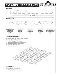
2 Panel Installation .. Dimensions ..Trim AssembliesFascia ..Mini Eave ..Eave Trim ..Rake ..Preformed Valley ..Transition ..Gambrel ..Hip ..Ridge ..Vented Ridge ..High Side Peak ..Side Wall ..End Wall ..Valley Lapping ..Valley Cutting ..Pipe Flashing ..Curb Detail ..Panel Endlap Detail ..45-89 101112131415161718192021222324252627-293 0R-Panel Install GuidePage 4 of 31 IntroductionThe R-Panel system is an industry leader in strength and durability. This heavy-duty roof and wallpanel features classic looks and is used primarily on commercial, industrial, and steel buildingapplications. R-Panel was designed with taller ribs to increase strength and allow installation on lowerslopes down to 1 is available in a range of paint colors and in both 26 and 24 gauge steel. It is also available inunpainted Galvalume . Our paint system carries a 40 year warranty and Galvalume a 25 year R-Panel system is available in 36 coverage.
3 The panel has four major support ribs at high thatadd rigidity and strength to the is a list of all of the R-Panel system approvals and certifications. Miami-Dade County, Florida Approved - See Approvals for Requirements Florida Building Code Approved - See Approvals for Requirements Texas Windstorm Certified UL 790 Fire Resistance Class A UL 2218 Impact Resistance Class 4 UL 580 Uplift Resistance Class 9036" "12"It is the users responsibility to verify all applicable code requirements for the area, check all measurements, and determine suitability of product for job. Implied warranties ofmerchantability and fitness for particular purpose are UNIFORM LOADS PER SQUARE FOOT - R and PBR PanelsNOTES: All load data is based on three or more spans (TS). For more information regarding spans or section properties, please contact your rep Allowable load based on stress is the smallest load due to bending, shear and combined bending and shear.
4 Allowable load based on deflection limit cannot exceed allowable load based on stress. These loads are for panel strength. Frames, purlins, fasteners and all supports must be designed to resist all loads imposed on the panel. Allowable uplift loads based on stress have not been increased by for wind uplift. Allowable loads for deflection are based on deflection limitation of span/180. For roof panels , self weight of the panel has to be deducted from the allowable inward load to arrive at the actual live load carrying capacity of the ksi2450 ksiAllowable Live Loads (lb/ft2) Allowable Uplift Loads (lb/ft2)Span (ft)SpanR-Panel Install GuidePage 5 of 31 Panel Installation GuideIf metal is not to be installed immediately, store inside in a well ventilated, dry location. Condensation or other moisture canform between the sheets during storage causing water stains or white rust which detracts from the appearance of the productand may affect the product s useful life.
5 Trapped moisture between sheets of painted metal can cause white rust to formunderneath the paint. This can cause the paint to flake off the panel immediately or several years later. To prevent white rustand staining, break the shipping bands on the material. Store the material on end or on an incline of at least 8 with asupporting board underneath to prevent sagging. Fan the sheets slightly at the bottom to allow for air circulation. Keep thesheets off of the ground with an insulator such as wood. Any outdoor storage is at the customer s own risk. If outdoorstorage cannot be avoided, protect the metal using a canvas cover or waterproof paper. Never cover the metal with plasticas this will cause condensation to that the structure is square and true before beginning panel installation. If the structure is not square, the panels willnot properly seal at the side laps. Green or damp lumber is not recommended. Moisture released from the damp lumber maydamage the metal panels .
6 Remove any loose metal shavings left on roof surface immediately to prevent corrosion. Keep rooffree of debris that could trap moisture on the metal, causing corrosion. The minimum pitch for roofing applications is 1 Installation InformationAlways wear heavy gloves when working with steel panels to avoid cuts from sharp edges. When power cutting or drillingsteel panels , always wear safety glasses to prevent eye injury from flying metal fragments. If you must walk on a metalroof, take great care. Metal panels can become slippery, so always wear shoes with non-slip soles. Avoid working on metalroofs during wet conditions when the panels can become extremely slippery. Walking or standing on a metal roof whichdoes not have a plywood or other deck beneath it is not recommended. However, if you must do so, always walk on thepurlins, never PrecautionsFasteningFigure 1If you wish to pre-drill fastener holes, use a cover sheet to prevent hot metalshavings from sticking to panels .
7 It is recommended that you cut panelsupside down using a nibbler. For best results, use #14 x 7/8 Lap Screws atpanel overlaps. For installation into a steel frame, use #12 x 1 (minimum)Self-Drilling Screws. For installation into a wood frame, use #10 x 1 (minimum) Wood Screws. Position fasteners as shown in Figure EAVE, RIDGE, & ENDLAPSFASTENERS INTERMEDIATE SUPPORTSFASTENING PATTERNS - ROOF APPLICATIONS FASTENING PATTERNS - WALL APPLICATIONSU nderdriven Overdriven CorrectLap Screws are optionalon Steeper SlopesLap Screws are optionalon Wall ApplicationsR-Panel Install GuidePage 6 of 31 Roofing Installation OptionsAllow an overhang a minimum of 1 at the eave toprovide for a drip edge. Use inside closure at eave toprevent water infiltration, insect or bird infestation atopenings. To protect against uplifting winds and toprovide a finished appearance, apply rake trim or otherstandard gable trim. Slopes of less than 1:12 aren trecommended.
8 For slopes less than 3:12, applybutyl tape as shown in Figure #4 along the top of alllap ribs. For best results, apply a 7/8 lap screw into thecrown of the rib to secure the side #5 Min. 6 LapInstall Metal Directlyto Wood/Metal Frame Use Maximum 2 Purlin Spacing Install Metal*DO NOT USE THIS OPTION FORHEATED SPACESI nstall Metal onSolid Deck Lay Plywood Deck Apply SyntheticUnderlayment or otherMoisture Barrier Protection Install MetalInstall Metal OverExisting Shingles ApplySyntheticUnderlayment or otherMoisture Barrier Protection Install MetalSyntheticUnderlaymentSyntheticUnder laymentEnd lap panels 6 . Install panels in the sequence shown in Figure # #4 - Rib OverlapR. PANEL OVERLAPPBR PANEL OVERLAPB utylTapeButylTapeR-Panel Install GuidePage 7 of 31 RidgeEaveRakeRake1 31234561342 Point APoint CRoof SlopeRidgeEaveRakeRakeRoof SlopePoint APoint C132 Point BUsing two tape measures, locate point C by hookingone tap to a nail at point A and the second tape to anail at point B.
9 Extend the tapes until they cross andmeet at 4 on the first tape and 5 on the second tapeand place a temporary nail where 4 and 5 4 and 5 measurements arethe 4 and 5 sides of the a line from point A to point B bytemporarily marking each point with a line must be parallel to the eave and inthis example 3 long (this is the 3 side of Triangle). Note:For larger multipleeach side of the triangle by the desiredincrease in size. For example, if the roofpanels are 25 from eave to ridge,multiply each side by a factor of 6 for an18 ..24 ..30 ..Triangle. Obviously, thecloser the triangle vertical leg length isto matching the panel length, thegreater the squaring a chalk line to point A and pull it inline with point C and mark a chalk line onthe roof will be the square reference line forthe panel MethodR-Panel Install GuidePage 8 of 31 EaveRidgeRakeRakeRoof Slope1 2 3 4 5 6 78 9 101 2 3 4 5 6 78 9 104 Square Reference LineRidgeRakeRakeEave1 251 2 Mark chalk lines parallel with the square referenceline out ahead of panel installation so that panelsquare can be checked as the panels are line spacing is one foot beyond 3 panelswide or about 10 for square by measuringthe distance from the installedpanel edge to the chalk line atboth the eave and ridge.
10 If themeasurements match, then theinstalled panels are square, if not,adjustments must be made tobring the panels back into MethodR-Panel Install GuidePage 9 of 31 AccessoriesTouch Up PaintPipe Boot(Various sizes, heat treated &retro fit also available)Tube SealantLP2 Vented Ridge Closure36 Outside Closure StripInside Closure StripDouble Bead Butyl Tape(7/8 x 3/16 x 40 or 25 depending on plant)Butyl Tape(3/8 x 3/32 x 45 )Flex-O-Vent Ridge Vent x 3 x 10 Synthetic RoofUnderlayment3/8 7/8 1 , 1- , 2 , 2- Hex Head Wood ScrewMetal-to-Wood1 , ., Hex Head Self DrillerMetal-to-MetalXL Emseal Expanding Hip/Valley x 1 x 13 2 Pop Rivet (Stainless)(1/8 x 3/16 )#7/8 Hex HeadLap Stitch ScrewMetal-to-Metal1 , , 2 Pancake HeadWood Screw1 , , 2 Pancake HeadSelf DrillerProfile Vent Ridge x 3 x 25 R-Panel Install GuidePage 10 of 31 RidgeRakeEaveValleyEndwallSidewallPitch BreakGambrelHigh Side PeakFascia / AngleOutside CornerInside CornerJ-ChannelRat GuardDrip CapFlat SheetTypical Trim Profiles (size/design vary by plant)