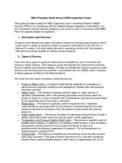
Transcription of Relief Valve - Autoclave
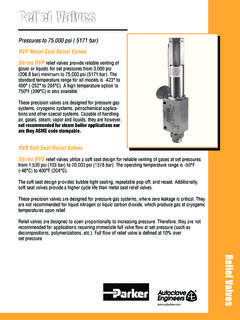
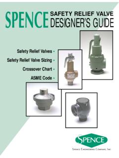
1 Relief ValveSeries RVP & RVS Operation and Maintenance ManualEnglish French German Catalog: 02-0031ME April 20162 Parker Autoclave EngineersInstrumentation Products DivisionErie, PA | Cat. 02-0031ME Table of ConTenTs page ENGLISH .. 2 FRENCH .. 5 GERMAN .. 8 CapSpring WasherSpringLock NutAdjusting BoltLock NutGasketSpindleSpringCylinder316 SS Plug3/4" NPTO utlet Connection316 SS SeatMounting " ( )Diameter316 SSValve Body316 SSSeat GlandInletConnectionNitronic 60 Plug GuideFigure 1 RVP SeriesCapSpring WasherSpringLock NutAdjusting BoltLock NutGasketSpindleSpringCylinderPlug Gland316 SS Seat316 SSValve Body316 SSSeat GlandArlonSoft SeatNitronic 60 Plug Guide3/4" NPTO utlet ConnectionMounting " ( )DiameterInletConnectionFigure 2 RVS Series3 Parker Autoclave EngineersInstrumentation Products DivisionErie, PA | Cat.
2 02-0031 MESection InformationThe Parker Autoclave Engineers Service RVP & RVS Relief valves for gas and liquid service are designed to protect systems and components against over-pressure and to reclose after normal pressure conditions are Parker Autoclave Engineers Relief Valve is factory tested for structural integrity and functionality. The Valve s relieving pressure is pre-set at the factory and is sealed with a wire tie to assure proper Valve operation when installed. The Valve is also tagged with set pressure and a maximum allowable working pressure and temperature. Note that the Relief Valve flow characteristics are defined at an allowable accumulation of 10% over set pressure.
3 It is good engineering practice to further protect against over-pressure with a rupture disc of sizeable PipingThe Relief Valve should be mounted in the vertical position and secured with mounting screws (customer supplied). The inlet tubing to the Valve should be unobstructed and as short as possible between the item being protected and the Relief Valve . valves other than the Relief Valve should not be permitted in the Relief line. Do not mount with outlet in upward position. The inlet tubing should have an inside diameter of at least that of the Relief Valve nozzle, but never less than the calculated minimum required relieving area.
4 All tubing should be clean and free of foreign matter and the connection to the Valve should be clean and well-lubricated with and anti-galling substance ( , Jet Lube SS-30) before installation. The inlet connection should be tightened to the recom-mend torque value listed in Parker Autoclave s Valve Fitting and Tubing Autoclave ENGINEERS FLUID COMPONENTS RESERVES THE RIGHT TO ALTER THE SPECIFICATIONS GIVEN IN THIS PUBLICATION IN LINE WITH OUR POLICY OF CONTINUOUS GENERAL TERMS AND CONDITIONS OF SALE, INCLUDING LIMITATIONS OF OUR LIABILITY, APPLY TO ALL PRODUCTS AND SERVICES PipingThe discharge piping from the Relief Valve should be direct and unobstructed.
5 Where possible, a short discharge pipe is desirable. However, if this is impractical, consideration of back pressure must be made by the customer. In any case, the discharge pipe should be at least the same inside diameter as the Relief Valve discharge NOTE: In the event that the Valve needs to be disassembled for repairs, it should be sent backto the factory since the warranty will be voided if the cable seal is broken. The following procedures should only be used if the warranty has expired. Refer to Figure 1 for part locations on the RVP Valve . For RVS valves , refer to Figure Cut the cable, then remove the Loosen the locknut on the adjusting bolt and turn the adjusting bolt counter-clockwise until all compression is relieved on the Loosen the spring cylinder locknut and remove the spring cylinder using a spanner Remove the top spring washer, spring and the botom spring washer from the Remove the spindle from the Remove the plug and plug guide from the body.
6 Remove the plug from the plug guide by remov-ing the locknut. For RVS Relief valves , remove the locknut from the plug gland and unscrew the plug gland from the plug guide using a 1/4 allen wrench. Then, remove the plug from the plug Remove the seat gland and the Inspect all parts for damage, especially the seat and plug. Replace as : Lubricate all threads with Jet Lube SS-30 or other appropriate lubricant. Refer to the Parker Autoclave Engineers VFT lubrication Place the Valve body into a Insert the seat into the body and screw in the seat Torque the seat gland to 75 ft-lbs. ( ) Place the plug into the plug guide so the plug threads extend out of the top of the plug guide.
7 For RVS valves , first place the plug in the plug guide as shown in Figure 2, then screw in the plug gland using a 1/4 allen Autoclave EngineersInstrumentation Products DivisionErie, PA | Cat. Tighten the locknut on the plug or plug gland threads using a 1/4 hex Clean the seat and the plug/plug guide Slide the plug guide on to the Take the spindle and place one of the spring washers on the spindle as shown in Figure 1. Be sure the flange on the spring washer faces upward toward the Assemble the spring on top of the spring washer along with the other spring washer. Be sure that the flange on the top spring faces downward.
8 Set this assembly Thread the locknut all the way up on the spring cylinder Thread the locknut all the way on the adjusting bolt. Thread the adjusting bolt into the spring cylinder and adjust it in about 1/4 . Carefully inset the assembled spring and spring washers and spindle into the spring Carefully assemble this into the Relief Valve body, making sure that the spherical bottom of the spindle is resting in the cavity of the plug or plug gland (see Figure 1 & 2). Tighten the spring cylinder into the Relief Valve body using a spanner wrench. It may be neces sary to tap the spanner wrench with a hammer to insure tight contact between the spring cylinder and the Relief Valve Tighten the locknut on the spring cylinder to 50 ft-lbs.
9 ( ) The Valve is now ready to have its set presure adjusted. Section Pressure AdjustmentNOTE: In order to accurately adjust the set pressure, an accurate pressure mea-surement device such as a transducer with digital readout or calibrated pressure gauge should be Attach the Valve inlet to the test Pressurize using nitrogen gas backed up by wa-ter until the Valve opens fully. The set pressure is adjusted with the adjusting bolt. Turn the adjust- ing bolt until the Valve opens at 5% over the set After this setting is found, bring the pressure slowly up to the specified set pressure using nitrogen gas backed up by water while checking for leaks through the seat with Leak-Tec.
10 The seat should begin to bubble at the specified cracking pressure. If it does not, vent the pressure from the Valve , readjust the bolt and repeat steps and Proceed to step if the cracking pres sure is Vent all pressure from the system and repeat step to verify that the pressure is The set pressure should be marked on a tag and attached to the Once the Valve has been set, tighten the locknut on the adjusting Place the gasket into the counterbore provided in the cap. Torque the cap to 50 ft-lbs. ( ) Expected accuracy once instructions are followed: +/- 3% of set pressure5 Parker Autoclave EngineersInstrumentation Products DivisionErie, PA | Cat.