Transcription of Temperature and Pressure Relief Valves - Watts Water
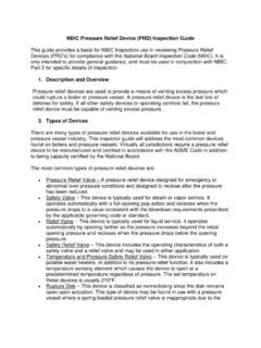
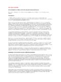
1 Series 1L, 1XL, 10L and 100 XLTemperature and Pressure Relief Rated*, CSA Listed. Self-closing T&P Relief Valves for Water Heaters up to 105,000 combined 2 in 1 T&P Relief valve provides the least expensive and proven means for protection against both excessive Temperature and Pressure emergency conditions. Provides fully automatic Temperature and Pressure Relief protection for hot Water storage tanks and heaters up to 105,000 BTU/HR. Series 10L furnished with test lever and short thermostat for installation directly in tank tapping. Series 100XL furnished with test lever and extension thermostat for installation in the hot Water outlet line or directly in the tank tapping. Temperature sensing element must be immersed in the Water within the top 6" (152mm) of the tank. Male inlet and female outlet. Temperature Relief 210 F (99 C). Standard settings 75, 100, 125, 150psi ( , , , bar).Features Series 1L, 1XL Size 1 2" 10L, 100XL Size 3 4" Rated*, CSA Listed Features a unique thermostat with special thermo-bonded coating 1L & 1XL Bronze body 10L & 100XL Brass body Stainless steel spring Thermostat is accurate and proven.
2 Exclusively designed and manufactured by WattsOptions For tanks and heaters with extra thick insulation, send for literature ES-SL100XL/L100XL/LL100XL/LLL100XL Series 100XL-8 with 8" (200mm) extension thermostat SOLAR - Model Z11 for stainless steel lever and 180 F (82 C) thermostat Series 1L, 1XL Size 1 2": For both Temperature and Pressure Relief protection. Series 1L has short thermostat and test lever. Series 1XL has extension thermostat with thermo-bonded coating. Also available with 8" (200mm) extension thermostat* Series 1L and 1XL Valves are not Listed or valvesEach Water heater and hot Water storage tank shall be equipped with a CSA and Rated* automatic Temperature and pres-sure Relief valve to protect the heater from excessive Pressure and Temperature . The device shall be ANSI certified. The BTU discharge capacity of the device shall be in excess of the BTU input rating of the heater. Watts Series 1L, 1XL, 10L or with governing authorities for local installation requirementsFor Water Heater and Hot Water Storage Tank ApplicationsES-10L/100 XLJob Name Contractor Job Location Approval Engineer Contractor s No.
3 Approval Representative Watts product specifications in customary units and metric are approximate and are provided for reference only. For precise measurements, please contact Watts Technical Service. Watts reserves the right to change or modify product design, construction, specifications, or materials with-out prior notice and without incurring any obligation to make such changes and modifications on Watts products previously or subsequently system operating Pressure must not exceed 75% of valve set information contained herein is not intended to replace the full product installation and safety information available or the experience of a trained product installer. You are required to thoroughly read all installation instructions and product safety information before begin-ning the installation of this installation, The valve lever MUST be operated AT LEAST ONCE A YEAR to ensure that the Water -ways are clear.
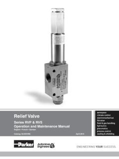
4 Certain naturally occurring mineral deposits may adhere to the valve, rendering it inoperative. When manually operating the lever, Water will discharge and precautions must be taken to avoid contact with hot Water and to avoid Water damage. BEFORE operating lever, check to see that a discharge line is connected to this valve directing the flow of hot Water from the valve to a proper place of disposal otherwise personal injury may result. If no Water flows, valve is inoperative. TURN OFF THE Water HEATER AND CALL A PLUMBER device is designed for emergency safety Relief and shall not be used as an operating !Dimensions WeightsSeries 1L, 1XL, 10L and 100 XLDirect Side TappingFor External Flue HeatersUse extra length extension thermostat to extend into Water storage Internal Flue HeatersUse short or standard length thermostat. Vertical discharge line must be installed with its direction Top Tapping For HeatersUse standard or extra length extension when the tappings are not providedUse standard or extra length extension 1452 2014 WattsUSA: T: (978) 689-6066 F: (978) 975-8350 : T: (905) 332-4090 F: (905) 332-7068 America: T: (52) 81-1001-8600 Temp.
5 M71 213 44331 2897 82225010284 15,0001XL-4 M71 213 44331 2897 822410012340 15,0001XL-8 M71 213 44331 2897 822820316454 15,00010L-2 M73 415 3240311 648113 16302508227 80,000100XL-4 M73 415 3240311 648113 163041008227105,000100XL-8 M73 415 3240311 648113 16308 2038227105,000A = overall width of the valve B = overall height of the valve, with lever closed, not including thermostat element length D = length of shank , from shoulder under outlet orifice overhang to inlet orifice edgeT = length of thermostat element, measured from inlet orifice edge to end of thermostat* 150psi set pressureREINSPECTION OF T&P Relief VALVE: Temperature and Pressure Relief Valves should be reinspected AT LEAST ONCE EVERY THREE YEARS by a licensed plumbing contrac-tor or authorized inspection agency, to insure that the product has not been affected by corrosive Water conditions and to insure that the valve and discharge line have not been altered or tam-pered with illegally.
6 Certain naturally occurring conditions may corrode the valve or its components over time, rendering the valve inoperative. Such conditions are not detectable unless the valve and its components are physically removed and inspect-ed. Do not attempt to conduct this inspection on your own. Contact your plumbing contractor for a reinspection to assure continuing safety. FAILURE TO REINSPECT THIS VALVE AS DIRECTED COULD RESULT IN UNSAFE Temperature OR Pressure BUILD-UP WHICH CAN RESULT IN SERIOUS INJURY OR DEATH AND/OR SEVERE PROPERTY !A Relief valve functions in an emergency by discharging Water . Therefore, it is essential that a discharge line be piped from the valve in order to carry the overflow to a safe place of disposal. The discharge line must be the same size as the valve outlet and must pitch downward from the valve and terminate at least 6" (152mm) above the floor drain where any discharge will be clearly visible. For 100DT discharge line consult your Watts