Transcription of Removing Ground Noise in Data Transmission Systems
1 Application Report SLLA268 October 2007. Removing Ground Noise in data Transmission Systems Thomas HPL - Interface ABSTRACT. Although it is commonly stated that isolating interfaces removes Ground potential differences (GPD) and Ground loops, it is also often unknown how and where these GPDs originate, what their waveforms or frequency content is, and why Ground loops can represent a real nuisance. This application report explains how electrical installation Systems , wired correctly (or incorrectly), in combination with time-varying loads can create large GPDs between remote transceiver stations. It also explains the frequency content of GPDs and demonstrates how to isolate a data Transmission system by avoiding Ground loops and GPDs that might adversely affect the quality of the Transmission signal.
2 It provides product examples for increasing tolerance to GPDs. Remote data links such as large computer networks in commercial buildings or fieldbus Systems in industrial networking can experience system lock-down and even destruction of network components due to dangerously high Ground Noise levels. The generation and/or existence of Ground Noise can have several sources such as: Large Ground potential differences (GPDs) due to the electrical installation system Large currents in the signal return and Ground wires due to the accidental design of Ground loops High voltage and current transients due to lightning, Ground fault conditions and induced Noise conducted or radiated from switching inductive loads Electrostatic discharges through human intervention during network installation or maintenance In contrast to high energy transients and electrostatic discharges, which only allow for the reduction of their potentially damaging effects through solid grounding and controlled discharge paths, Ground potential differences and Ground loops can be proactively avoided through careful system design.
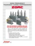
3 This application report therefore explains where GPDs originate and how Ground loops are created unintentionally. The document also gives an example of a robust data Transmission design that prevents both Noise sources from occurring by using electrically isolated transceiver stations. SLLA268 October 2007 Removing Ground Noise in data Transmission Systems 1. Submit Documentation Feedback The Electrical Installation The Electrical Installation Figure 1 shows a simplified electrical installation with the secondary windings of a -Y transformer as supply. Load A. Main Circuit Load B. Utility Transformer Meter Panel Board Breaker L1 L2. N. L3. Secondary only Load C. E1 E2 E3. Figure 1. Basic Electrical Installation The four wires leaving the transformer include the three phase conductors L1, L2, and L3 and the neutral conductor N (dotted line), which serves as return path for the ac phase currents.
4 The wires run through the meter and the main circuit breaker to the panel boards, where they are split into separate load groups, ( , A, B, and C). A fifth wire, the protective earth conductor PE (green) connects the equipment chassis within a load group together and provides a low-impedance, fault-current path back to the source (transformer) during a Ground -fault condition. Low impedance ensures sufficiently high fault-current to activate an overcurrent protection device, which removes high touch-voltage from faulty equipment. Earthing Earthing has two main objectives: Providing a solid reference potential (ideally 0 V) to the electrical installation system via a low-impedance connection to earth Protecting buildings and equipment exposed to lightning by diverting lightning strikes straight to earth The grounding electrode E1 in Figure 1 grounds the center point of the transformer secondary, providing earth reference potential to the neutral conductor.
5 Depending on the transformer's location, E1 might also protect against lightning. Because utility transformers rarely provide a PE conductor and because voltage drops due to large neutral current can occur between the transformer and the service entrance, a second grounding electrode E2 is used to Ground the supply system within the building. The structure of this electrode can be a metal rod, a metal water pipe system , or the metal frame of the building, provided that the latter two are in direct contact with earth for at least 10 feet. Grounding electrodes in the form of water pipes and building frames also connect to the PE conductor at various locations within the building to ensure stable reference potential throughout the installation system .
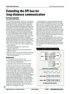
6 Lightning protection is provided through electrode E3. This type of electrode usually has the structure of a long metal rod that must exceed the height of a building or outdoor equipment by a specified length. For lightning strikes, E3 provides a low-impedance path to earth. To further reduce the electrical impedance of the lightning-current path, the national electric code (NEC) requires that these electrodes also connect to the building's grounding system . 2 Removing Ground Noise in data Transmission Systems SLLA268 October 2007. Submit Documentation Feedback Linking Grounds Many low-impedance connections between PE conductors and grounding electrodes in combination with multiple high-impedance paths between grounding electrodes and the line impedance of the conductors themselves create a highly complex impedance network, (see Figure 2), and currents flowing through it cause differing Ground potentials at the various interconnections of this network.
7 Electrodes Neutral Load Load A1 An PE. Water pipe Load Load B1 Bn E1 E2 E3. Earth impedance Figure 2. Complex Impedance Model of a Grounding Network Literature often attributes the generation of Ground potential differences to lightning or Ground -fault conditions, but rarely mentions their existence during normal operation. The situation is further obscured by the National Electric Code (NEC) describing the PE as a currentless conductor, which would negate the existence of Ground potential differences. That these assumptions are far from reality is discussed in the following sections. Currents in the neutral and the PE conductors can create GPDs ranging from small-to-large values depending on the type of loads connected to the installation and on the type of earthing system installed.
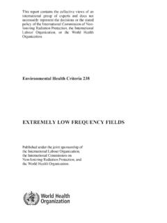
8 Linking Grounds The link between the direct current (DC) Ground of your local electronic circuit and the earth reference potential of the mains is usually provided by the local, power supply that converts the line voltage into the required DC output. Figure 3 shows a simplified block diagram of a low-cost, switched-mode power supply (SMPS), typically used in personal computers, laser printers, and other equipment. L1 FB. FS1 R1 T1 D2 FS2. L +V. EMI & R2. RF S1. FILTER C1 C2. D3 C3 RL. N Q1. VGD D1. I leak PE 0V. Figure 3. Simplified Block Diagram of an SMPS. The DC Ground of the SMPS output is referenced to the protective earth (PE) conductor of the mains via the SMPS chassis. This direct link therefore acts as a sense wire, establishing the voltage at the PE.
9 Conductor as the local DC Ground potential. SLLA268 October 2007 Removing Ground Noise in data Transmission Systems 3. Submit Documentation Feedback Linear and Nonlinear Loads Linear and Nonlinear Loads Large office and industrial buildings operate a vast amount of nonlinear loads, such as PCs, laser printers, solid-state heater controls, fluorescent tubes, uninterruptible power supplies (UPS), and variable speed drives (VSD). In comparison to linear loads such as incandescent lamps, whose phase currents maintain a sinusoidal waveform, nonlinear loads distort phase currents, introducing large harmonic content. (see Figure 4). = + +. Distorted current wave form Fundamental 3rd harmonic 5 th harmonic Figure 4. Distorted Phase Current and Its Frequency Components Whereas the third and fifth harmonics of the fundamental 60-Hz line frequency comprise the majority of the harmonic content, the vector sum of all frequency components (including the 60-Hz fundamental) can reach peak values that exceed the amplitude of the fundamental phase current by more than 100%.
10 All neutral conductors merge into one neutral conductor of large diameter within the distribution panel running towards the transform (see Figure 5). In the case of linear loads, the neutral currents of different phase Systems cancel each other to a certain extent and only a fraction of total neutral current remains due to loading imbalance (see Figure 5). Total neutral current Sinusoidal phase currents due to load imbalance Figure 5. Sinusoidal Phase Currents and Total Neutral Current for Linear Loads For nonlinear loads however, the individual currents add to a total neutral current primarily consisting of third harmonic content (see Figure 6). + + =. Fundamental current in comparison Phase-1 Phase-2 Phase-3 Total Neutral Figure 6. Total Neutral Current Mainly Consists of Third Harmonics The large neutral currents of nonlinear loads, therefore, cause significantly higher voltage drops across the line resistance of the electrical installation than those of linear loads.