Transcription of Repair Information - Eaton
1 January 2010 Eaton Hydrostatic PumpsSeries 1 Models 33-64 Hydrostatic Variable PumpsRepair Information2 Table of ContentspageIntroduction .. 2ID Tag .. 3 Required Tools .. 3 Exploded View Drawing and Part Names .. 4 Disassembly .. 6 Reassembly .. 12 Appendix A: IPOR End Cover .. 23 Appendix B: Power Limiter Valve End Cover .. 24 Seal Removal .. 20 Installing the New Seal .. 21 Appendix C: Control Orifice Installation and Removal .. 25 Appendix D: Charge Pump Repair .. 26 Appendix E: Special Tools .. 27 Hydraulic Fluid Requirements .. 29 IntroductionThis manual provides service Information for Eaton Models 33 thru 64 Variable pumps . Step by stepinstructions for the complete disassembly, inspection and reassembly of the pump are given.
2 The followingrecommendations should be followed to insure successful repairs: Most repairs require the removal of the pump from the vehicle. Cleanliness is extremely important. Clean the port areas thoroughly before disconnecting the hydraulic lines. Plug the pump ports and cover the open hydraulic lines immediately after they re disconnected. Drain the oil and clean the exterior of the pump before making repairs. Wash all metal parts in clean solvent. Use compressed air to dry the parts. Do not wipe them dry with paper towels or cloth; Lint in ahydraulic system will cause damage. The compressed air should be filtered and moisture free. Always use new seals when reassembling hydraulic pumps .
3 For replacement parts and ordering Information refer to parts list 6-608. Lubricate the new rubber seals with a petroleum jelly like Vaseline before installation. Torque all bolts over gasketed joints, then repeat the torquing sequence to make-up for gasketcompression. Verifying the accuracy of pump repairs on an authorized test stand is CorporationHydraulics DivisionSpencer, Iowa 51301 RotationSerial 00 - 00000 00 000000A - Displacement ( )0033 = = = = = = - Identifies Type of Product21 =Variable Displacement Pump31 =Fixed Displacement Motor41 =Variable Displacement Motor61 =Tandem Variable DisplacementPumpsC - Identifies Specific Unit ConfigurationD - Month of ManufactureE - Year of ManufactureF - Specific Serial Number of UnitG - Identifies Direction of Input Shaft( pumps Only) RotationObserved from Shaft End of UnitCW = ClockwiseCCW = CounterclockwiseEFACBGDR equired ToolsID Tag 9/64 in.
4 Hex Key 1/4 in. Hex Key 1/2 in. Socket 9/16 in. Socket 5/8 in. Socket 3/4 in. Socket 7/8 in. Socket 1 in. Socket 1-3/8 in. Socket Dial Indicator with Magnetic Base Spring Compression Scale (0-10 lbs) No. 5 or 7 Retaining Ring Pliers Small Pair of External Retaining Ring Pliers(45 or 90 ) Adjustable joint Pliers 3 1/4-20 Bolt Breaker Bar or Ratchet Wrench Torque Wrench (200 lb-ft capacity) 18 to 20 in. Adjustable Wrench Shaft End Spacer (Special) Hammer ( steel and Plastic) Depth Micrometer with Extensions Parallel Bars Slide Hammer Split Blade Bearing Puller Prick Punch Scribe Punch Arbor Press Clean, Lint Free Cloths Loctite Light Petroleum Jelly Suitable Solvents and Cleaners Rotating Seal Puller (Special) Low Clearance Bearing Puller (Special) Bearing Cone Driver (Special) Check Valve Puller (Special)Special Tools are shown on pages 25 and Char-Lynn HP 30 Motor C-MOLO-TM012-E December 20092 Exploded View DrawingGasket(s)Charge PumpMounting Bolts54515285339404148525049442322212088 CW PropelCW StandardValve PlateGasket(s)
5 Control Valve/Port Plate forSlave ControlMounting Bolts1914 1615131237384567117103178971282932703435 30423643845464745 Models 33 thru 64 Variable Pump laeS tfahS1smihS noinnurT23 1gnir-O dna gulP434niP832gnir-O932gnir-O0442 Servo Sleeve Retainer26wercS paC34 1revoC dnE742gnir-O946tloB revoC dnE254 Mounting Flange Bolt125 Shipping Strap26 Mounting Flange S/A11puC gniraeB79niP lewoD81teksaG egnalF gnitnuoM910 Drive Shaft S/A111 Replacement Bearing Kit 1A/S etalphsawS2113 Thrust Plate114 Rotating Group115 Piston and Slipper S/A91etalP reniateR reppilS6119 Retaining Strap and Bolts21lerraB rednilyC0221 Bearing Plate11etalP evlaV2223 Control Valve Option128 Trunnion Bolt629 Trunnion S/A230 Replacement Bearing Kit Parts used as Housing136 Servo Piston S/A237 Retaining Ring841 Servo Sleeve244 End Cover Gasket145 End Cover Bearing146 Shaft Shims48 Check Valve S/A250 Back-up Ring253 End Cover Bolt254 Charge Pump170 Plug and O-ring1 Hydrostatic Variable Pump Repairs6 DisassemblyDue to the complexity of the heavy duty pump certainsubassemblies are disassembled, inspected, andreassembled upon removal from the pump.
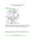
6 Thisprocedure insures Repair accuracy and helps avoid theloss of small Clean the exterior of the pump and drain the Position the pump so the shaft seal is : Shaft seal removal procedure 3-6 apply to pumps built before September 1999, as indicated by the date code on the pump. For pumps which have a date code after 1999, go to step 105 on page 20 to remove the shaft Using a retaining ring pliers remove the retaining 14 Screw a 3 in. X 1/4-20 bolt into the threaded hole inthe stationary seal. Pull on the bolt to remove the Use the special pulling tool, Owatonna Tool Co. P/NCAS 1844, to remove the rotating seal, see figure 1. Ifthe special tool is not available pull out the rotating sealwith a wire bent to the shape of the : Detailed drawings of all special tools are given inAppendix E, in the back of this Remove the o-ring; it will either be in the rotating sealor on the : If you are just replacing the shaft seal jump aheadto step 109 on page Remove the six hex head bolts that hold the controlvalve to the Lift the control valve away from the pump anddisengage the feedback linkage, see figure Remove the control valve Inspect the control valve: Start by thoroughlyflushing the control valve with clean solvent.
7 Then blowit dry with compressed air. Be sure to blow through all ofthe control valve s internal the control valve linkage. Move the control leverback and forth; it should move freely without should be no free play in the feedback link orcontrol the control valve orifice; if it is plugged afterflushing clean or replace it. Appendix C givesinformation on orifice 2 Important: The control orifice may beinstalled in different locations dependingon which pump control is used. If it isremoved a new orifice must be installedin the same ValveGasketFeedbackLinkageRetaining RingRetaining Ring PliersStationary SealRotating SealO-ringO-ringBoltPulling Tool714 Pull the two check valves from the end cover.
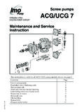
8 Hookthe short end of the pulling tool in one of the check valvecross holes, see figure the pulling tool is unavailable remove each check valveby inserting a screw driver into the output port and pryingup on the bottom of the check : A detailed drawing of the check valve pulling toolin given in Appendix Remove the o-rings and back-up rings from thecheck 4 Check ValvePulling ToolCheck ValveScrewDriverFigure 311 Reposition the pump so the shaft is vertical and thecharge pump is on top. Stand the pump on two blocksof wood as shown in figure Remove the four bolts that hold the charge pump tothe end cover, see figure 3. The two remaining boltshold the charge pump : Information on charge pump Repair is given inAppendix Lift the charge pump from the end cover.
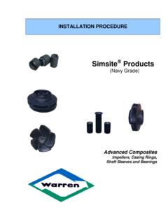
9 Removethe gasket and two dowel : Keep track of the dowel pins, see figures 3, 5,and 8. There is a total of nine dowel pins in the pump. Itis a good idea to put them in a small box so they don tget Pin (9)GasketBolt (4)Hydrostatic Variable Pump Repairs8 Figure 5 GasketShimsBearingCupDowel PinValve PlateBearingPlate16 Remove the end : The cylinder barrel spring pre-load willdamage the pump s internal parts if the end cover isremoved by removing six of the eight bolts that hold the endcover to the pump. Leave two bolts that are directlyacross from each other , loosen the two remaining bolts one or two end cover should rise as the bolts are loosened. If itdoesn t tap it with a plastic hammer to break the the gasket seal is broken loosen the boltsgradually and evenly until the cylinder barrel spring pre-load is the bolts and lift the end cover from the careful; do not drop the valve plate, it may lift awaywith the end : Use care when handling the pump s internalparts.
10 They are machined to extremely close Turn the end cover over and set it on a clean : Always protect machined : The standard end cover is shown in figure optional end covers are available. Use the sameremoval procedure for the optional end of the optional end covers are shown in theappendices:18 Remove the valve plate and dowel pin; they willeither be on the end cover or bearing : Pump valve plates are unidirectional and must bematched to the input direction of the pump. Themetering slots indicate the valve plate s direction, seefigure 6. Also be aware that there are different shapedmetering slots; V shaped metering slots are standard,and kidney shaped metering slots are on propel The bearing cup is slip-fit into the end cover.