Transcription of Repair Information - Eaton
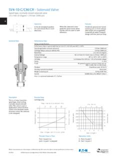
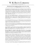
1 Eaton . February, 1997. hydrostatic Transaxle Repair Information Model 778. Right Angle Transaxle hydrostatic Transaxle Model 778 Right Angle Transaxle Retaining Ring (Internal Woodruff Key Shaft, Input (S/A). Retaining Ring (External). Fan/Sleeve (S/A) Barb Fitting Seal, O-ring Input Shaft Seal, Screw Control Self Shaft Tap Axle Cover Housing (S/A) Short Bushing Dowel Button Hex Flange Screw Pump Rotor Ball Axle Insert Piston Housing (S/A) Long Cam Ring Control Shaft Piston (S/A). Hex Flange Screw Ball Spring Brake Ball Motor Shaft Piston Rotor Seal Spring Gasket Adapter Pin Screw Housing Self Tap Spring Friction Actuator Pad (1 or 2. Piece). Gasket Seal Adapter Push Filter Pin 2. hydrostatic Transaxle Model 778 Right Angle Transaxle Bearing, Ball Retaining Ring Retaining Retaining Ring Ring Axle Shaft Slotted Axle Housing Axle Housing Hex S/A Short Nut Woodruff Bearing, Ball Key Seal, Radial Retaining Lip Ring Retaining Ring Thrust Axle Housing Washer Axle Housing S/A Long Thrust Washer Retaining Ring Slotted Bearing, Ball Hex Nut Axle Shaft Seal, Woodruff Radial Key Lip Retaining Ring Sun Gear 1st Sun Gear 2nd Reaction Plate Backup Plate Secondary Carrier Ring Gear Planet Gear 1st Primary Carrier Ring Gear Planet Gear 2nd 3.)
2 hydrostatic Transaxle Model 778 Right Angle Transaxle 6 The following tools are required for disassembly and reassembly of the transaxle. 3/8 in. Socket or End Wrench 1 in. Socket or End Wrench Ratchet Wrench Torque Wrench 300 lb-in [34 Nm]. 5/32 Hex Wrench Small screwdriver (4 in. [102 mm] to 6 in. [150 mm] long). No. 5 or 7 Internal Retaining Ring Pliers No. 4 or 5 External Retaining Ring Pliers 1 The following Repair Information applies to the Eaton 788 Piece of Pipe or Hydraulic Tubing series hydrostatic transaxles. (1 in. x 6 inches long). Piece of Pipe or Hydraulic Tubing Assembly Date of (1-1/8 in. [29 mm] x 6 in. [150 mm] long). Part Number Input Rotation Build Code Small Arbor or Hydraulic Press (CW or CCW) 3 or 4 Large Rubber Bands Customer Light Petroleum Jelly (such as Vaseline). Part Number XXX-XXX XXX XXXXXX Factory ( if Required ) XXXXXX XXXXXX 11 Rebuild Molybdenum Grease Code Loctite 518 Master Gasket Original Build Factory Rebuild ( example - 010195 ) ( example - 010195 11 ) 7 Seal all open ports before cleaning.
3 Thoroughly clean the 01 01 95 01 01 95 11 transaxle exterior. Year Number of Day Year Times Note: It is best to drain the transaxle through the case drain Day Rebuilt (2). Month port with the input shaft in the horizontal position. Month 2 The transaxle identification Information is located opposite Axle Housing (S/A) and Planetary Assemblies the input shaft, on the back of the housing assembly. (Long). 3 The build code of the transaxles identifies the month, day and year of the transaxle manufacture. This Information is found in the same area as the identification code. 4 When ordering replacement parts for a transaxle, the part(s) order must include the part name, part number, Hex Flange Screws (8). quantity of parts and also the transaxle model number, input rotation and date code. Transaxles 788 (Short). 5 The following procedures describe complete disassembly Hex Flange Screws (8). and reassembly of the transaxle. The level of cleanliness maintained while servicing the transaxle could affect its performance.
4 Work in a clean area. After disassembly, wash Axle Housing Disassembly all parts with clean solvent and blow the parts dry with air. Inspect all mating surfaces. Replace any damaged parts that 8 Use a 3/8 inch socket or end wrench to remove the eight hex could cause internal leakage. Do not use grit paper, files or flange screws from the axle housing assembly. grinders on finished parts. 9 After removing the flange screws, carefully remove the axle Note: Whenever a transaxle is disassembled, our recommen- housing assembly from the housing assembly. dation is to replace all seals. Lubricate the new seals with petroleum jelly before installation. Use only clean, recom- Caution: Retain the planetary assemblies in the axle housing mended hydraulic fluid on the finished surfaces at reassembly. assembly during removal. 4. hydrostatic Transaxle Model 778 Right Angle Transaxle Axle Housing Disassembly Long 12 Reposition the axle housing with the splined end of the axle in the up position.
5 Using a No. 4 or 5. (Short) external retaining ring pliers, remove the retaining Axle Housing (S/A) ring and thrust washer from the axle shaft. (Long). 13 Remove the axle from the axle housing by using a small press or by tapping the splined end of the axle shaft with a plastic head hammer. This will dislodge the seal and bearing from the axle housing. 14 After separating the axle shaft from the axle housing, remove the ball bearing, seal and thrust Planetary Assemblies washer from the axle shaft. The thrust washer may be in the axle housing. Note: The retaining ring remaining on the axle shaft need not be removed. 10 To disassemble the axle housing assembly, carefully position the axle housing assembly on a clean flat surface, Axle Housing Disassembly Short then separate axle housing from the planetary assemblies as shown. 15 Position the axle housing assembly with the output end of the axle shaft in the up position. Using Axle Housing a No.
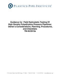
6 5 or 7 internal retaining ring pliers, remove the ball bearing retaining ring from the axle housing. Axle Shaft with One Retaining Ring Remaining 16 Position the axle housing assembly with the output end of the axle shaft in the down position. Remove the spacer from the splined end of the axle Retaining Ring shaft Thrust 17 Using a No. 5 or 7 internal retaining ring pliers, Thrust Washer Washer remove the bearing retaining ring from the inside of Radial Lip Seal the axle housing. Retaining Bearing, Ball Ring 18 Remove the axle from the axle housing by using a small press or by tapping the output end of the axle shaft with a plastic head hammer. This will dislodge the inside bearing from the axle housing. Woodruff Bearing, Ball Key 19 After removing the axle shaft out the back side of Retaining the axle housing, drive the remaining bearing out the Ring Spacer front of the axle housing. Retaining Ring 20 Remove seal from the axle housing, drive seal Axle Shaft with One toward and out the back side of housing.
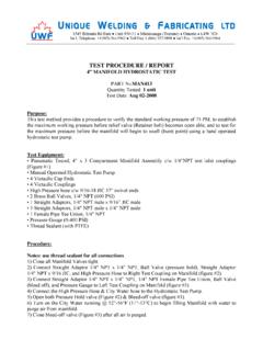
7 Retaining Ring Remaining 21 Remove and replace bearing if necessary using a Radial Lip Seal No. 4 or 5 external retaining ring pliers, remove one Bearing, Ball Axle Housing retaining ring from axle shaft then drive bearing off of the shaft. Note: The retaining ring remaining on the axle shaft 11 Position the axle housing assembly with the output end of need not be removed. the axle shaft in the up position. Using a No. 5 or 7 internal retaining ring pliers, remove the ball bearing retaining ring from the axle housing. 5. hydrostatic Transaxle Model 778 Right Angle Transaxle 28 Next, remove the backup plate and reaction plate from the primary sun gear. 29 Remove the primary sun gear from the motor rotor Ring Gear assembly. 30 Remove the small friction brake pad assembly from its Secondary Carrier Planet Gears, Second recessed pocket located in the adapter (brake shaft section). 31 Shown in previous drawings are the three major parts used Sun Gear, Second in the Eaton transaxle wet brake assembly: the friction pad assembly, reaction plate and backup plate.
8 When the brake is applied, the rotating reaction plate is squeezed between the Ring Gear stationary friction pad and the backup plate. 32 Remove the gasket from the adapter (brake shaft section). Primary Carrier Planet Gears, First Note: This gasket may have remained on the axle housing. 22 To disassemble the planetary assemblies for inspection and 33 Remove the 4 self tap screws from the adapter (brake shaft cleaning, first remove the ring gear (from the secondary section), and remove this section and the gasket from motor carrier/planet gears). rotor end of housing. 23 Next, putting a slight squeeze on the secondary carrier 34 This adapter (brake shaft section) contains a pin to retain planet gears, remove the three secondary planet gears and the brake shaft; drive this pin out and remove brake shaft. carrier. Shaft seal can be removed and replaced. Install brake shaft and pin. 24 Turn the assembly over and remove the secondary planet gears for inspection and cleaning.
9 Motor Rotor Disassembly 25 Remove the sun gear and remaining ring gear. 35 Important: Be extremely careful when removing the motor rotor assembly. The ball pistons are spring loaded in 26 Again, putting a slight squeeze on the remaining carrier the bores and must remain intact because each ball piston planet gears, remove planet gears and carrier from the backup is matched to its respective bore. plate. The best way to remove the motor rotor assembly is to place a 27 Shown above are both the primary and secondary carrier separate motor race on top of the existing motor race in the assemblies. The planet gears may be removed for inspection housing assembly. Hold the separate race securely in and cleaning. position. Then carefully pull the motor rotor assembly outward until the ball pistons are fully engaged in the groove Pin Brake Shaft located in the center of the separate race. Carefully remove Seal the rotor assembly and race together as a set, handling the motor rotor assembly only.
10 Self Tap Screw (4). Gasket Motor Rotor/Ball (S/A). Friction Pad Backup Plate Note: If a separate motor race is not available, work a wide rubber band around the outside of the motor rotor to hold the Gasket ball pistons in their bores. Motor Sun Rotor/Ball (S/A) 36 It is essential that the ball pistons be retained in their bores Gear with Rubber Band during handling. This is especially true for the motor rotor(s), Reaction Plate (First) Adapter Ball Retainer as the motor ball pistons are spring loaded in the bores. 6. hydrostatic Transaxle Model 778 Right Angle Transaxle Retaining Ring Pump Rotor/Ball (S/A) with Rubber Input Shaft (S/A) Band Retainer Barbed Hose Fitting Control Shaft Control Shaft Insert Input Shaft Seal Cam Ring (S/A). Control Shaft Seal Self Tap Screw (7) Relief Valve Spring and Ball Cover Cam Ring Pivot Dowel Hollow Dowel Button (2). 46 Remove the control shaft and insert from the housing and cam ring assembly. 47 Remove the cam ring insert from the control shaft.