Transcription of Replacing and Setting - Eaton
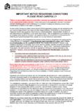
1 InstallationInformationEaton CorporationHydraulics Operations15151 Hwy. 5 Eden Prairie, MN 55344 Telephone 612/937-7254 Fax 612/937-7130 Eaton DivisionGlenrothes, FifeScotland, KY7 4 NWTelephone +44(0)1592-771-771 Fax +44(0)1592-773-184No. 0 4-1 132 October, 1999 Copyright Eaton Corporation, 1999 All Rights ReservedPrinted in USAR eplacing and Setting1)Move up locknut, washer and o-ring onto speed sensor to allowfull exposure of sensor threads as posible. See Figure 12)Align a piston with the center of the sensor port. See Sensor PortView Figure )By hand, ligthly thread speed sensor body into the housing untilthe sensor touches against the motor piston. Do not force thesensor against the piston, damage may occur. See Figure the sensor has contacted the piston before the washertouches the )Position sensor by turning it out (CCW) until sensor alignmentnotchs are at a right angle 3 to motor centerline and then backout sensor one full turn or 360 . Retain sensor at this positionand torque locknut to 8,5-14,1 N m [75-125 lbf in].
2 See Figure Duty SeriesEaton MotorModel 74300w/ SpeedSensorAlignmentNotchSpeed SensorPistonLock NutSensor Side ViewFigure 3 PistonSpeed SensorSpeed SensorRightPositionSensor Port ViewFigure 2 WrongPositionMoveLock Nut,Washer & O-ringUp on TreadsFigure 1 Figure 490 Alignment NotchAlignment NotchAlignment NotchsPerpendicular toCenterline of MotorAlignment NutHex Head Parallel withCenterline of Motor Shaft