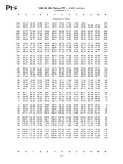
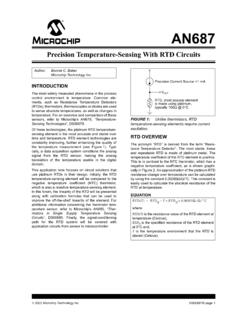
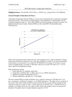
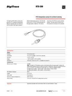
Transcription of Resistance Temperature Detectors (RTD)
1 4949 Delemere Ave., Royal Oak, Michigan 48073 Phone (800) 876-4442 Fax (248) 280-099850A96. Sheath Material (See page 14 for other Materials) 4 = 304SS (1650oF)(Std) 0 = 310SS (2100oF) 6 = 316SS (1650oF) I = INCONEL (2150oF) HeadFittingOption-FixedBushing A B FittingOption NPTB ushingOption 1C ConnectionHeadOption-CastIron B TipStyle-RoundTip G ConnectionHeadOption-Aluminum A HeadFittingOption- NPTHexNipple G TipStyle-FlatTip F RH N1 2 3 4 5 6 7 8 9 10 11 12 13 14 Resistance Temperature Detectors (RTD)Style H Connection Head Assembly4. Sheath Operating Temperature2. RTD Element Type Material Resistance Temp. Coefficient A = platinum (Std) 100 ohms @ 0oC .00385 ohm/ohm/oC B = platinum 100 ohms @ 0oC .00392 ohm/ohm/oC C = platinum 500 ohms @ 0oC .00385 ohm/ohm/oC D = platinum 1000 ohms @ 0oC.
2 00385 ohm/ohm/oC F = Nickel 120 ohms @ 0oC .00672 ohm/ohm/oC G = Copper 10 ohms @ 25oC .00427 ohm/ohm/oC H = NiFe 604 ohms @ 0oC .00519 ohm/ohm/oC3. Tip Style / Element Accy. (See Diagram TS-RTD) .01% .02% .03% .05% .10% .50% Flat Tip: M L K P F(Std) I J Round Tip: H E D A G B C Vented Tip: Q U T W V R S4. Configuration (See Diagram RTD) A = 2 Wire - Single Element D = 4 Wire - Dual Element* B = 3 Wire - Single Element(Std) E = 6 Wire - Dual Element* C = 4 Wire - Single Element Z = Other5. Sheath Operating Temperature A = -200 C to 260 C (500oF)(Std) C = -200 C to 600 C (1200oF) B = -200 C to 400 C (750oF) Z = Other7. Sheath Diameter (Metric sizes also available) G = .125* I = .250* M = .375 H = .188* Q = .313 Z = Other*Not available for all head styles*Quick delivery F 1. Connection Head (See page 19 for other C-Heads) A = Aluminum G = 316 Stainless Steel B = Cast Iron S = 316SS Explosion Proof C = FMCUS Alum. EXP V = Dan D = Poly Black - Chain Y = APEX Aluminum EXP E = FDA Ploy - Latch (Consult Factory for Specialty Web: Email: H Connection Head AssemblyE = FDA Poly - LatchH = FDA Poly - Chain D = Black Poly - ChainF = Nylon HeadB = Iron HeadC = Cast Aluminum EPS = 316 Stainless Steel EPA = AluminumM = Alum.)
3 MiniatureQ = Nylon MiniatureR = CanisterV = Dan HeadO = Open Ceramic BlockG = 316 Stainless CONNECTION HEAD OPTIONS11. Fitting Location F (inches from tip) N = No Fitting Location (Std)13. Bend Angle (See Page 49 for more information) N = None(Std) G = 45 Degree Bend S = 90 Degree Bend Z = Other HEAD MOUNTING FITTINGSD iagram HFFixedBushing(Std)FixedHexNippleSingleM aleNPTD oubleMaleNPTFor more Connection Head options go to 9. Head Mounting Fittings (See Diagram HF) A = Fixed Bushing (No process threads) (Stainless) (Std) P = Pipe Nipple (specify in notes) N = None Z = Special Compression Fitting Connection 1/8 NPT 1/4 NPT 1/2 NPT Hex Nipple Connection 1/4 NPT 1/2 NPT 3/4 NPT Fixed Hex Nipple (Steel) F G H Single Male NPT (Stainless) - - S Fixed Hex Nipple (Stainless) I J K Double Male NPT (Stainless) W X Y 14.
4 Bend Location C (inches from tip, see Diagram BEND page 49) N = No Bend(Std)8. Sheath Length L (Example = 12-1/2 inches) - inches Z = greater than inches (Consult Factory)CONFIGURATION (RTD)Diagram RTDFor a larger selection of RTD Assemblies go to: 12. Special Options (Choose all that apply - See Page 17 for more Options) N = None B = RTD Transmitter* (See page 71) C = Programmable Transmitter* (See page 71) H = High Vibration K = Copper Tip I = SS ID Tag M = MgO Construction P = Electro-etching Q = Ground Screw S = Spring Loaded T = Coated Probe Y = Certificate of Conformance 6 = Tip Sensitive Element Z = Special (Consult Factory)*Not available for all head styles 10. Fittings (See page 18 for more info and other fittings) (Metric fittings also available)N = None (Std) FB = Fixed Bayonet Fitting (.188 and .250 Dia only) Z = Special NPT Fittings 1/8 NPT 1/4 NPT 1/2 NPT SPECIAL Fixed Bushing (Stainless) 1A 1B 1C 1Z Compression (Brass) one time adj.
5 5A 5B 5C 5Z Compression (Stainless) one time adj. 6A 6B 6C 6Z Compression (Stainless) re-adjustable* 7A 7B 7C 7Z *Teflon gland standard (400oF) for other gland options such as Lava (1200oF) see page 18 Explosion ProofQ = Oversized AluminumNEWSTYLEWeb: Email: principal of the Resistance Temperature detector (RTD) is not nearly as complex as that of a thermocouple. Basically, the principal of operation depends on the fact that the electrical Resistance of metals varies directly with Temperature , and is reproducible to a high degree of accuracy. The curve of Temperature versus Resistance for a given wire material can thus be predicted by employing a constant, known as the Temperature coefficient of Resistance . Useful sensitive elements of RTD S are those which show a Resistance Temperature relationship of acceptable magnitude. Two such metals are platinum and s are commonly used in sensitive areas requiring much tighter accuracy than thermocouples.
6 But accuracy is dependent on the RTD leadwire configuration. Leadwire error can have a significant effect on accuracy. Adding leadwire between the RTD and control will add additional Resistance to readings. Since Resistance increases with Temperature it is not recommended to use a 2-wire RTD when a high accuracy is configuration is the least accurate RTD configuration. The lead wire Resistance is not compensated for by the transmitter or controller. The increased Resistance will cause Temperature to be higher than the actual configuration is the most commonly used. The added lead wire Resistance is calculated by the control through a third wire. The leadwire Resistance is then subtracted from the loop Resistance and true Resistance is given. Through this method the controller or transmitter compensates the lead wire giving an accurate Temperature display. 4-wire configuration provide slightly better compensation, but are generally found only in laboratory equipment and other areas where high accuracy is required but must be used in conjunction with a 4-wire Temperature Detectors (RTD)Stainless Steel SheathTypical 3-Wire Probe ConstructionCeramicEncapsulatedElementGa p for ExpansionJunction - Copper Leads Tack Welded or Sliver BrazedTeflon or Glass InsulatedStainless Steel SheathTypical High Temperature 3-Wire Probe ConstructionCeramicEncapsulatedElementMg O FilledJunction - Nickel LeadAlumina InsulatorsJunction - Copper LeadsTack Welded or Sliver BrazedTeflon or Glass Insulated Copper LeadsStainless Steel SheathCeramicEncapsulatedElementJunction Junction - Copper LeadsTack Welded or Sliver BrazedTypical 3-Wire MgO Probe Construction(High Vibration/HighTemperature)CeramicorEpoxy FilledTransition(Moisture Barrier)
7 Teflon or GlassInsulatedDiagram RTDRTD AssembliesGIC Thermodynamics sales and engineering staff will assist you with designing the best RTD sensor style to fit your process and application. Selecting the proper sensor style is very important, as each application or process has its own specific inherit problems that require careful consideration in order to determine the sensors life, accuracy, and dependability. When choosing a sensor it is important to consider its loca-tion, Temperature range, accuracy required, how rapidly the Temperature cycles, heat conduction, process environment, vibration, and ease of installation. If you need additional assistance with the selection of a sensor for your application, please feel free to contact our sales and engineering staffWeb: Email: Options Special Options (T/C and RTD s): Chose as many special options needed. If you require two of the same option like two Weld Pads or ID tags put a letter for each item required.
8 Option A - Special Limits of Error (T/C only): This qualifies the accuracy of the sensor based on specified standard test points (EMF vs Tempera-ture) set by the industry. This designates the highest tolerances available. (See page 13 for more info.)Option B - RTD Transmitter: Head mounted transmitter, fully Linearized, Pt100 input only. Mp82800R (See page 70 for more info.)Option C - Programmable RTD Transmitter: Head mount transmitter, fully linearized. Push-button Programmable, can be programmed in the field. Pt100 RTD 3-wire input only. Mp82850R. (See page 70 for more info.)Option D - Universal Transmitter: Scalable over the entire range of 8 RTD s and 12 Thermocouples. Fully-Isolated; Fully-Linearized. Hart protocol option. Mp82700 (See page 70 for more info.)Option E - Economy Multi-input transmitter: Pt100 RTD & Thermocouples. Fully-linearized head mount transmitter. Mp82800. ( page 66 )Option F - Field Bendable: Sensor is able to be bent in the field.
9 This option must be specified for Rigid Tube assemblies, T/C and RTD. Mineral Insulated (MgO) assemblies are field bendable option not G - Shielded leadwire: Shield with Drain Wire Reduces Electrical Noise. (Specify -Shield open or Shield grounded to probe)Option H - High Vibration: Assemblies are reinforced to help prevent damage/failure in extreme I - SS ID Tag: Product Identification plate. (Electro-etching standard)Option J - Coated Armor: Provides a moisture seal for this durable and abrasion resistant wire protection. PVC or K - (Open)Option L - Mating Connector: Assembly will be supplied with a mating M - MgO Construction: Metal sheathed mineral insulation provides best construction for high Temperature or heavy vibration ap-plications. Multiple sizes and O - Separate Ungrounded: Isolated junction type used in dual and triplex MGO assemblies (See Diagram JT page 15.)Option P - Electro-etching: Part number or other information permanently etched on probe Q - Ground Screw: For head assemblies if a ground screw is required.
10 Not available on all connection head R - Faster Response Construction: Greatly increases response time in ungrounded/Isolated S - Spring Loaded: Allows probe retraction for best contact with process surface. Pressure on the junction tip provides and main-tains faster T - Coated Probe: Sheath is sealed with Teflon or PVC to provide added protection in highly corrosive applications. Option U - Butt Welded Junction: Optional welding procedure of wire thermocouples instead of twist V - Field Cuttable: RTD probes can be cut down to a minimum 3 length using a standard tube cutter. Sealed construction for out-door/moisture applications. Also available on some Thermocouple assemblies. Option W - Weld Pad: Tig welded to sheath. Formed to match tube diameter. Used to weld sensor to process surface. (See page 16)Option X - X-Ray Junction: Sensors are x-rayed in two or four planes for weld integrity and junction Y - Certificate of Conformance or Calibration: Conformance certifies the material being provided meets the specifications and requirements of the purchase order.