Transcription of Rosemount 3051S Series Pressure Transmitter - …
1 Manual Supplement00809-0200-4853, Rev ABNovember 2017 Rosemount 3051S Series Pressure Transmitterwith FOUNDATION Fieldbus ProtocolOverview .. page 1 Configuration .. page 2 Installation .. page 5 Operation and maintenance .. page 5 Troubleshooting .. page 5 Advanced Pressure Diagnostics for Foundation Fieldbus .. page manual is intended to be used as a supplement to the Rosemount 3051S Series Pressure Tr a n s m i t t er w i t h FOUNDATION Fieldbus Protocol Reference Manual when option code IT6 has been selected. This manual supplement provides information on configuring, installing, operating, maintaining, and troubleshooting the Rosemount 3051S Series Pressure Transmitter with FOUNDATION Fieldbus communications.
2 See Ta b l e 1 and Figure 1. Device Driver InformationRelease dateDevice identificationDevice driver identificationReview instructionsReview functionalityNAMUR hardware revision(1)1. NAMUR Revision is located on the hardware tag of the device. Differences in level 3 changes, signified above by xx, represent minor product changes as defined per NE53. Compatibility and functionality are preserved and product can be used software revision(1)FOUNDATION Fieldbus software revisionFOUNDATION Fieldbus universal revisionDevice revision(2)(3)2. FOUNDATION Fieldbus device revision can be read using a FOUNDATION Fieldbus capable configuration tool.
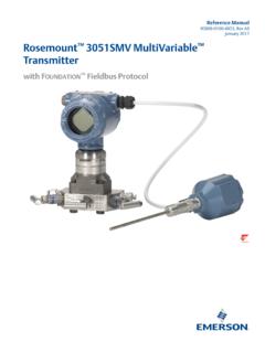
3 Value shown is minimum revision that could correspond to NAMUR Device driver file names use device and DD revision. To access new functionality, the new Device Driver must be downloaded. It is recommended to download new Device Driver files to ensure full functionality. Manual document numberChange Field Diagnostics, Mass Flow RemovedDec-08N/ , Alert Repor ting, Block Instantiation, Common Software DownloadSep-01N/ Product Release2 Manual Supplement00809-0200-4853, Rev ABRosemount 3051S Series Pressure TransmitterNovember 2017 Rosemount 3051S Series Pressure TransmitterFigure 1.
4 Transmitter Data recycling/disposalRecycling of equipment and packaging should be taken into consideration and disposed of in accordance with local and national Configuration For complete configuration details using Fieldbus, reference the Rosemount 3051S FOUNDATION Fieldbus Reference configurationDisplay configurationThe following configuration items are found in the LCD display Transducer Transmitter features a three-line display. The first line of five characters displays the output description, the second line of seven digits displays the actual value, and the third line of six characters displays engineering units.
5 The LCD display meter can also display diagnostic parameter configured for display will appear on the LCD display for a brief period before the next parameter is displayed. Up to four different variables may be shown on the LCD display meter is preconfigured to show the measured variables that correspond to the Transmitter configuration. It can be configured to display any measured or calculated value that has a status parameter with it ( FOUNDATION Fieldbus DS-65 parameter type). Configure each parameter for display as stated parameter selectThe display of each configured parameter can be turned on or off by editing the Display Parameter Select parameter.
6 Parameter options include Pressure , module temperature, bar graph, and scaled scaled variable configuration allows the user to create a relationship/conversion between the Pressure units and user-defined/custom typeEnter the Block Type for the block that contains the parameter to be tagEnter the Block Tag of the block that contains the parameter to be communications output3 Manual Supplement 00809-0200-4853, Rev ABRosemount 3051S Series Pressure TransmitterNovember 2017 Rosemount 3051S Series Pressure TransmitterParameter indexEnter the Block Index of the parameter to be tagEnter up to five characters to be displayed on the top line of the LCD display when this parameter is typeSelect auto when the parameter to be displayed is Pressure or percent.
7 The units of the parameter will be read and automatically displayed on the LCD custom to display up to six characters as configured in the Custom Units none if the parameter is to be displayed without associated unitsIf the Units Type is set to custom specify up to six characters to be displayed with the configured capabilitiesGeneral block information Reference information on the process control function blocks can be found in the Function Block Reference active schedulerThe Rosemount 3051S can be designated to act as the backup Link Active Scheduler (LAS) in the event that the LAS is disconnected from the segment.
8 As the backup LAS, the Rosemount 3051S will take over the management of communications until the host is restored. The host system may provide a configuration tool specifically designed to designate a particular device as a backup are a total of 20 Virtual Communication Relationships (VCRs). One is permanent and 19 are fully configurable by the host system. Twenty-five link objects are available. See Ta b l e 2 and Ta b l e 3 o n page Supplement 00809-0200-4853, Rev ABRosemount 3051S Series Pressure TransmitterNovember 2017 Rosemount 3051S Series Pressure TransmitterTable 2.
9 Network ParametersHost timer recommendationsT1 = 96000T2 = 9600000T3 = 480000 Table 3. Block Execution TimesNetwork parameterValueSlot Time6 Maximum Response Delay4 Maximum Inactivity to Claim LAS Delay5 Minimum Inter DLPDU Delay7 Time Sync class4 (1ms)Maximum Scheduling Overhead10 Per CLPDU PhL Overhead4 Maximum Inter-channel Signal Skew0 Required Number of Post-transmission-gap-ext Units0 Required Number of Preamble-extension Units1 BlockTime (in ms)Analog Input20 PID25 Arithmetic20 Input Selection20 Signal Characterizer20 Integrator20 Output Splitter20 Control Selector205 Manual Supplement 00809-0200-4853, Rev ABRosemount 3051S Series Pressure TransmitterNovember 2017 Rosemount 3051S Series Pressure For complete configuration details using Fieldbus, reference the Rosemount 3051S FOUNDATION Fieldbus Reference and maintenance For operation and maintenance details using Fieldbus, reference the Rosemount 3051S FOUNDATION Fieldbus Reference For complete troubleshooting details using Fieldbus.
10 Reference the Rosemount 3051S FOUNDATION Fieldbus Reference section provides summarized troubleshooting suggestions for the most common operating problems on the Rosemount 3051S Series Pressure Transmitter with FOUNDATION a malfunction is suspected despite the absence of any diagnostic messages on the communicator display, follow the procedures described to verify Transmitter hardware and process connections are in good working order. Always deal with the most likely and easiest-to-check conditions messagesProcedures and instructions in this section may require special precautions to ensure the safety of the personnel performing the operations.