Transcription of Rosemount 3051SMV MultiVariable Transmitter - …
1 Reference Manual00809-0100-4853, Rev ABJanuary 2017 Rosemount 3051 SMV MultiVariable Transmitterwith FOUNDATION fieldbus ProtocoliiiReference Manual 00809-0100-4853, Rev ABContentsJanuary 2017 Contents 1 Section 1: Using this manual .. Product overview .. Product recycling/disposal .. 2 2 Section 2: Section overview .. Safety messages.. Flow configuration.. Engineering Assistant ver. 2 .. Installing Engineering Assistant ver. 2 Stand-Alone.. Launching Engineering Assistant ver. 2 and connecting to the Transmitter .. Creating a flow configuration.. Sending a flow configuration to the Transmitter .. Mass flow test calculation .. Variable configuration .. Units configuration .. Mass flow .. Differential pressure .. Static pressure.
2 Process temperature .. Variable simulation .. Device configuration .. Display configuration.. Write lock .. Device capabilities .. General block information .. Link active scheduler .. Capabilities .. Node address .. Block instantiation .. 16 3 Section 3: Section overview .. Safety messages.. Considerations .. 18 ContentsivReference Manual00809-0100-4853, Rev ABContentsJanuary General .. Mechanical .. Environmental .. Steps required for quick installation .. Mount the Transmitter .. Tagging .. Consider housing rotation .. Rotate the LCD display .. Set the switches .. Wire, ground, and power .. Signal wiring and shield grounding .. Power supply .. Power conditioner .. termination.
3 Optional process temperature input (Pt 100 RTD Sensor) .. Rosemount 305 and 304 Manifolds .. Rosemount 305 Integral Manifold installation procedure .. Rosemount 304 Traditional Manifold installation procedure .. Manifold operation.. 32 4 Section 4: Operation and Section overview .. Safety messages.. Calibration.. Calibration overview .. Sensor trim overview .. Determining necessary sensor trims.. Types of pressure trim .. Restore factory calibration .. Differential pressure sensor calibration .. Static pressure sensor calibration .. Process temperature sensor calibration.. Field upgrades and replacements .. Disassembly considerations .. Housing assembly including electronics board.. Terminal block .. LCD display.
4 Flange and drain vent .. 45vReference Manual 00809-0100-4853, Rev ABContentsJanuary 2017 Contents 5 Section 5: Section overview .. Safety messages.. Measurement troubleshooting .. Fill fluid .. Communication troubleshooting .. Alarms and conditions .. Service support.. 53 AAppendix A: Specifications and Reference Specifications .. Performance specifications .. Functional specifications.. Physical specifications .. Dimensional drawings .. Ordering information .. Spare parts list .. 72 BAppendix B: Product European Directive Information .. Ordinary Location Certification .. Installing Equipment in North America .. Installation drawings .. 87viReference Manual00809-0100-4853, Rev ABContentsJanuary 2017 ContentsviiReference Manual 00809-0100-4853, Rev ABTitle PageJanuary 2017 Title PageRosemount 3051S MultiVariable TransmitterThe products described in this document are NOT designed for nuclear-qualified applications.
5 Using non-nuclear qualified products in applications that require nuclear-qualified hardware or products may cause inaccurate information on Rosemount nuclear-qualified products, contact the local Emerson Sales who handle products exposed to a hazardous substance can avoid injury if they are informed of and understand the hazard. If the product being returned was exposed to a hazardous substance as defined by OSHA, a copy of the required Material Safety Data Sheet (MSDS) for each hazardous substance identified must be included with the returned this manual before working with the product. For personal and system safety, and for optimum product performance, make sure the contents are fully understood before installing, using, or maintaining this technical assistance, contacts are listed below:Technical support, quoting, and order-related questionsUnited States - 1-800-999-9307 (7:00 am to 7:00 pm CST) Asia Pacific- 65 777 8211 Europe/Middle East/Africa - 49 (8153) 9390 Equipment service needsNorth American Response Center1-800-654-7768 (24 hours includes Canada)Outside of these areas, contact the local Emerson Manual00809-0100-4853, Rev ABTitle PageJanuary 2017 Title PageExplosions could result in death or serious injury.
6 Do not remove the Transmitter cover in explosive atmospheres when the circuit is live. Verify the operating atmosphere of the Transmitter is consistent with the appropriate hazardous locations certifications. Before connecting a communicator in an explosive atmosphere, make sure the instruments in the segment are installed in accordance with intrinsically safe or non-incendive field wiring practices. Both Transmitter covers must be fully engaged to meet explosion-proof to follow these installation guidelines could result in death or serious injury. Make sure only qualified personnel perform the installation. Electrical shock could cause death or serious injury. If the sensor is installed in a high-voltage environment and a fault or installation error occurs, high voltage may be present on the Transmitter leads and terminals.
7 Use extreme caution when making contact with the leads and leaks could result in death or serious injury. Install and tighten all four flange bolts before applying pressure. Do not attempt to loosen or remove flange bolts while the Transmitter is in equipment or spare parts not approved by Emerson for use as spare parts could reduce the pressure retaining capabilities of the Transmitter and may render the instrument dangerous. Use only bolts supplied or sold by Emerson as spare assembly of manifolds to traditional flange can damage sensor module. For safe assembly of manifold to traditional flange, bolts must break back plane of flange web ( , bolt hole) but must not contact module module and electronics housing must have equivalent approval labeling in order to maintain hazardous location approvals.
8 When upgrading, verify sensor module and electronics housing certifications are equivalent. Differences in temperature class ratings may exist, in which case the complete assembly takes the lowest of the individual component temperature classes (for example, a T4/T5 rated electronics housing assembled to a T4 rated sensor module is a T4 rated Transmitter .)Reference Manual 00809-0100-4853, Rev ABIntroductionJanuary 20171 IntroductionSection this manualThe sections in this manual provide information on installing, operating, and maintaining the Rosemount 3051S MultiVariable FOUNDATION fieldbus Transmitter (3051 SMV). The sections are organized as follows: Section 2: Configuration provides instruction on commissioning and operating the Rosemount 3051 SMV and information on flow configuration and device configuration.
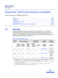
9 Section 3: Installation contains mechanical and electrical installation instructions. Section 4: Operation and Maintenance contains operation and maintenance techniques. Section 5: Troubleshooting provides troubleshooting techniques for the most common operating problems. Appendix A: Specifications and Reference Data supplies reference and specification data, as well as ordering information. Appendix B: Product Certifications contains intrinsic safety approval information, European ATEX directive information, and approval overviewThis manual covers the Rosemount 3051 SMV FOUNDATION fieldbus Transmitter . The device measures differential pressure, static pressure and process temperature and has the capability to calculate mass following transmitters are covered in this 1-1. Rosemount 3051 SMV Fully Compensated Mass Flow (M) TransmitterMeasurement typeDescription1 Differential pressure, static pressure, temperature2 Differential pressure and static pressureTable 1-2.
10 Rosemount 3051 SMV Process Variables Only (P) TransmitterMeasurement typeDescription1 Differential pressure, static pressure, temperature2 Differential pressure and static pressure2 Reference Manual00809-0100-4853, Rev ABIntroductionJanuary 2017 IntroductionFigure 1-1. Transmitter Data recycling/disposalRecycling of equipment and packaging should be taken into consideration and disposed of in accordance with local and national 1-3. Device Driver InformationRelease dateDevice identificationDevice driver identificationReview instructionsReview functionalityNAMUR hardware revision(1)NAMUR software revision(1)FOUNDATION fieldbus software revisionFOUNDATION fieldbus universal revisionDevice revision(2)(3)Manual document numberChange : Initial Product Release1. NAMUR Revision is located on the hardware tag of the device.