Example: marketing
ROVER SERIES 20A | 30A | 40A
constant current mode, delivering its maximum current to the batteries (MPPT Charging) . Float Charge: After the constant voltage stage, the controller will reduce the battery voltage to a float voltage set point. Once the battery is fully charged, there will be no more chemical reactions and all the charge current would turn into heat or gas ...
Tags:
Information
Domain:
Source:
Link to this page:
Documents from same domain

MT -50 Remote Tracer Meter - Renogy Official Site
www.renogy.com1 MT -50 Remote Tracer Meter RENOGY Remote Tracer Meter for Commander Series and ViewStar Series Charge Controllers 2775 E. Philadelphia St., Ontario CA 91761

ViewStar Series - Renogy
www.renogy.com2 • Be careful when working with large lead acid batteries. Wear eye protection and have fresh water available in case there is contact with the battery acid.

1. 2. pg. 2 3. 4. 5. 6. 7. 8. 9. 10. - solar panel kits
www.renogy.com4 The RENOGY Starter and RV Kits come with a PWM- type charge controller to optimally charge your batteries from solar power. Each charge controller comes with a separate detailed manual. It is recommended that you read the solar charge controller manual in detail.

BT-1 BLUETOOTH MODULE - Renogy
www.renogy.comBluetooth 4.2 and BLE technology provides fast and uninterrupted communication Embedded exclusive Bluetooth chip with high efficiency and low energy consumption Connects to our user-friendly smart phone App, Renogy DC Home, to keep track of your system 02

BATTERY - Renogy
www.renogy.comONLY charge the battery with a battery charger or charge controller that is compatible with lithium iron phosphate batteries. Depending on the length of time between manufacturing and shipping, the battery may be received at a partial state of charge. Please fully charge the battery prior to the initial use.

DCC1212-20 | 40 | 60 - Renogy
www.renogy.comWiring and Fusing Depending on the application, the grounding point may differ. Cable Length/ Min AWG Model Cable Recommended Fuse To DC Input (Starter) DCC-1212-20 DCC-1212-40 10AWG 8-6AWG 6-4AWG 30A or close 8AWG 8-6AWG 4AWG 50A or close 12AWG 10-8AWG 6AWG DCC-1212-60 To DC Output (House) To DC Input (Starter) To DC Output (House) To …
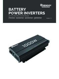
BATTERY POWER INVERTERS - Renogy
www.renogy.comThis manual contains important safety, installation, and operating instructions for the inverter. The following symbols are used throughout the manual: Inverter Safety The inverters are suitable for 12V Battery Banks ONLY. ALWAYS make sure …

Dual Input DC-DC - Renogy
www.renogy.comThe Renogy Dual Input DC-DC On Board Battery Charger w/ MPPT is designed to charge your ... Mount the Battery Charger ... The charger may be mounted on the cabin of tthe vehicle, along a chassis rail, the inner guard of a vehicle, behind the grille or headlight or even on the side of the radiator. However, you want to make sure that the area is ...
Related documents

Automotive Battery Chargers Battery Constant Voltage ...
www.centurybatteries.com.auThis method charges a battery at a maximum voltage, typically from 13.8V to 15V and a maximum current depending on the charger specification. When a “flat” battery has been charged for a period of time and the maximum voltage is approached, the charge current drops off in proportion to the battery voltage increase. Constant Current Charging

Chapter 6: Voltage Regulator - Ajlon Tech
www.ajlontech.comSince the Zener voltage is constant, the increase in V o ... in input voltage or load current caused by a change in load resistance, the decrease is sensed by R 1 and R 2. A feedback voltage obtained from voltage divider R 1 and R 2 is applied to …

Response of First Order RL and RC Circuits
courses.egr.uh.eduFrom the current-voltage relationship for an inductor, we know that the at constant current, inductor acts like a short. Thus, the resistors R and R S have no current flowing through them, so the only current flowing is through the inductor, and i L = i S. Now we look at the situation for t > t 0. The switch has been

Determination of Planck’s Constant Using the Photoelectric ...
web.mit.eduSep 25, 2007 · A back current was a noticeable effect for several wave-lengths. Back current is caused by photoelectrons liber-ated from the platinum anode as a result of scattered light. Its effects become most prominent when the re-tarding voltage is high. The retarding voltage is seen as an accelerating voltage by these electrons and they travel

The Bandgap Reference
www.seas.ucla.eduis that the op amp does not drive resistors and can thus maintain a high loop gain. The Basic Idea As mentioned in the pre - vious section, the volt-age across a pn junction and hence the base-emitter voltage, V BE, of a bipolar transistor exhibit a negative TC. It can be shown that, for a constant collector current, BE /, T V T Vm BE 4 VE Tg q ...

A Guide to Understanding Battery Specifications
web.mit.eduFor a battery with a capacity of 100 Amp-hrs, this equates to a discharge current of 100 Amps. A 5C rate for this battery would be 500 Amps, and a C/2 rate would be 50 Amps. Similarly, an E-rate describes the discharge power. A 1E rate is the discharge ... then constant voltage charging, allowing the

Operational Amplifier Circuits
ocw.mit.eduA current to voltage converter is an op amp circuit which accepts an input current and gives an output voltage that is proportional to the input current. The basic current to voltage converter is shown on Figure 5. This circuit arrangement is also called the transresistance amplifier. Iin R Vout N1 Figure 5. Current to voltage converter

MT-033: Voltage Feedback Op Amp Gain and Bandwidth
www.analog.comThis tutorial examines the common ways to specify op amp gain and bandwidth. It should be noted that this discussion applies to voltage feedback (VFB) op amps—current feedback (CFB) op amps are discussed in a later tutorial (MT-034). OPEN-LOOP GAIN . Unlike the ideal op amp, a practical op amp has a finite gain. The open-loop dc gain (usually
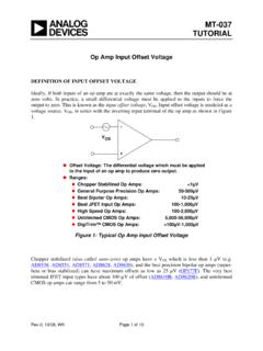
MT-037: Op Amp Input Offset Voltage - Analog Devices
www.analog.comInput offset voltage varies with temperature, and its temperature coefficient is known as TCVOS, or more commonly, drift. Offset drift is affected by offset adjustments to the op amp, but when the offset voltage of a bipolar input op amp has been minimized, the drift may be as low as 0.1 µV/°C (typical value for