Transcription of RS-232 INTERFACE - TSCM
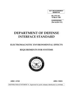
1 Frame (Chassis) GroundTransmit dataReceive dataSignal GroundRequest to sendCarrier detectData set readyRing indicatorData terminal readyTransmit dataReceive dataRequest to sendCarrier detectData set readyRing indicatorData terminal ready123745862220 Clear to sendClear to send123745862220 COMPUTERTERMINALRS-232 1. Direct-to-computer RS-232 InterfaceRS-232 INTERFACEI ntroduction:The RS-232 INTERFACE is the Electronic Industries Association (EIA) standard for the interchange of serial binarydata between two devices. It was initially developed by the EIA to standardize the connection of computers with telephoneline modems. The standard allows as many as 20 signals to be defined, but gives complete freedom to the user. Threewires are sufficient: send data, receive data, and signal ground. The remaining lines can be hardwired on or offpermanently.
2 The signal transmission is bipolar, requiring two voltages, from 5 to 25 volts, of opposite Standards:The industry custom is to use an asynchronous word consisting of: a start bit, seven or eight data bits, an optionalparity bit and one or two stop bits. The baud rate at which the word sent is device-dependent. The baud rate is usually150 times an integer power of 2, ranging from 0 to 7 (150, 300, 600 ,.., 19,200 ). Below 150 baud, many system-uniquerates are used. The standard RS-232 -C connector has 25 pins, 21 pins which are used in the complete standard. Many ofthe modem signals are not needed when a computer terminal is connected directly to a computer, and Figure 1 illustrateshow some of the "spare" pins should be linked if not needed. Figure 1 also illustrates the pin numbering used in the originalDB-25 connector and that now commonly used with a DB-9 connector normally used in modern computersSpecifying compliance to RS-232 only establishes that the signal levels in two devices will be compatible and thatif both devices use the suggested connector, they may be able to be connected.
3 Compliance to RS-232 does not imply thatthe devices will be able to communicate or even acknowledge each other's 1 shows the signal names, and functions of the RS-232 serial port pinout. Table 2 shows a complete pin descriptionTable 1. RS-232 Serial Port PinoutNamePinSignal NameFunctionAA1 PGThis line is connected to the chassis ground of the GPIB-232CV. Since theProtective GroundGPIB-232CV chassis ground is not connected to earth ground, pin 1 should beconnected on both serial line carries serial data from the GPIB-232CV to the serial DataBB3 RxDThis line carries serial data from the serial host to the DataCA4 RTSThis signal line is driven by the GPIB-232CV and when asserted indicates thatRequest to Sendthe GPIB-232CV is ready to accept serial data. The GPIB-232CV unassertsRTS when it is no longer ready to accept serial data because of a buffer signal line is asserted by the serial host and sensed by the GPIB-232CV.
4 Clear to SendWhen asserted, it indicates that the serial host is ready to accept serial data. When unasserted, it indicates that data transmission should be line establishes a reference point for all INTERFACE GroundCD20 DTRThis signal line is asserted by the GPIB-232CV to signal that it has beenData Terminalpowered on, and is ready to 2. RS-232C INTERFACE Ground10(Reserved for Data Set Testing)19 Secondary Request to Send2 Transmitted Data11 Unassigned20 Data Terminal Ready3 Received Data12 Sec. Rec'd. Line Sig. Detector21 Signal Quality Detector4 Request to Send13 Sec. Clear to Send22 Ring Indicator5 Clear to Send14 Secondary Transmitted Data23 Data Signal Rate Selector(DTE/DCE Source)6 Data Set Ready15 Transmission Signal Element Timing24 Transmit Signal Element(DCE Source)Timing (DTE Source)7 Signal Ground (Common16 Secondary Received Data25 UnassignedReturn)8 Received Line Signal17 Receiver Signal Element TimingDetector(DCE Source)9(Reserved for Data Set 18 UnassignedTesting) Characteristics: The RS-232 -C specifies the signaling rate between the DTE and DCE, and a digital signal is usedon all interchange circuits.
5 The RS-232 standard specifies that logic "1" is to be sent as a voltage in the range -15 to -5 Vand that logic "0" is to sent as a voltage in the range +5 to +15 V. The standard specifies that voltages of at least 3 V inamplitude will always be recognized correctly at the receiver according to their polarity, so that appreciable attenuationalong the line can be tolerated. The transfer rate is rated > 20 kbps and a distance of < 15m. Greater distance and datarates are possible with good design, but it is reasonable to assume that these limits apply in practice as well as in load impedance of the terminator side of the INTERFACE must be between 3000 and 7000 ohms, and not more 3, summarizes the functional specifications of the most important 3. RS-232 -C Circuit DefinitionsNameFunctionDirectionto:Data Signals Transmitted Data (BA)DCEData generated by DTE Received Data (BB)DTEData Received by DTET iming signals Transmitter Signal Element Timing (DA)DCEC locking signal, transitions to ON and OFF occur at center of each signal element Transmitter Signal Element Timing (DB)DTEC locking signal, as above; both leads relate to signals on BA Receiver Signal Element Timing (DD)DTEC locking signal, as above, for circuit BBControl Signals Request to Send (CA)DCEDTE wishes to transmit Clear to Send (CB)DTEDCE is ready to transmit.
6 Response to request to send Data Set Ready (CC)DTEDCE is ready to operate Data Terminal Ready (CD)DCEDTE is ready to operate Ring Indicator (CE)DTEI ndicates that DCE is receiving a ringing signal on the communication channel Carrier Detect (CF)DTEI ndicates that DCE is receiving a carrier signal Signal Quality Detector (CG)DTEA sserted when there is reason to believe there is an error in the received data Data Signal Rate Selector (CH)DCEA sserted to select the higher of two possible data rates Data Signal Rate Selector (CI)DTEA sserted to select the higher of two possible data ratesGround Protective Ground (AA)NAAttached to machine frame and possibly external grounds Signal Ground (AB)NAEstablishes common ground reference for all circuitsRange: The RS-232 -C standard specifies that the maximum length of cable between the transmitter and receiver shouldnot exceed 100 feet, Although in practice many systems are used in which the distance between transmitter and receiverexceeds this rather low figure.
7 The limited range of the RS-232C standard is one of its major shortcomings compared withother standards which offer greater ranges within their specifications. One reason why the range of the RS-232C standardis limited is the need to charge and discharge the capacitance of the cable connecting the transmitter and receiver. Mechanical Characteristics: The connector for the RS-232 -C is a 25 pin connector with a specific arrangement of theory, a 25 wire cable could be used to connect the Data Terminal Equipment (DTE) to the Data CommunicationEquipment (DCE). The DTE is a device that is acting as a data source , data sink, or both, a terminal, peripheral orcomputer. The DCE is a device that provides the functions required to establish, maintain,and terminate a data-transmissionconnecting, as well as the signal conversion, and coding required for communication between data terminal equipment anddata circuit; a modem.
8 Table 4, shows the complete summary of the RS-232 -C, , descriptor, sponsor, data format, 4. Summary of the RS-232 -CData Format5- to 8- bit serialTransfer TypeAsynchronousError HandlingOptional Parity BitConnector25-pin female connector on DCE; 25-pin male connector on DTEL ength20 metersSpeed20 kb/sRemarksRS-232 is used in the microcomputer world for communications between two DTEs. The null-modem is included into one or both connecting devices, and/or cable and is seldom documented. As a result, establishing an RS-232 connection between two DTEs is frequently a difficult task.