Transcription of RTD 100 Ohm Installation Manual - Thermometrics Corporation
1 RTD 100 Ohm Installation Manual Resistance Temperature Detectors Assemblies, together with their accessories, are sensitive instruments which must, be handled carefully. They contain, even if not visible from the outside, glass and or ceramic parts which are susceptible to damage. Therefore, always handle them with care. Page 1 of 6. 2009. TABLE OF CONTENTS. Introduction ..3. Specifications .. 3. Installation ..4. Repair and Maintenance ..5 - 7. Thermometrics manufactures and stocks a variety of products to meet your temperature measurement requirements Copyright, 2009. Thermometrics Corporation 18714 Parthenia Street Northridge, California 91324. Telephone (818) 886-3755, Fax (818) 772-7690. e-mail Page 2 of 6. 2009. xx xx Introduction Thermometrics Corporation Resistance Temperature Detectors (RTD's) are manufactured to conform to;. American (.00385), European (.00385), Japanese (.)
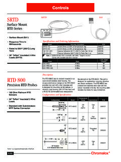
2 003916), Balco (.00518,) Copper (.00427), or Nickel (.00672). temperature coefficients. Temperature sensor types include 10, 100,120, 500 and 1000 ohm instruments. Specifications STANDARD SPECIFICATIONS FOR Thermometrics RTD's Unless otherwise specified, Resistance Temperature Detectors conform to the following specifications: - platinum 100 ohm @ 0 C (per IEC-751, Class B Accuracy). - Temperature Coefficient = .00385 (per IEC-751 and ASTM E-1137). - Temperature Range: 0 to 250 C. - 3-Wire configuration: 22 AWG Ag Coated Cu Stranded. - Teflon Insulation. - Lead length = 12 . - Lead wire ends stripped and tinned approximately long. - Stainless steel sheath; +.004 / " per ASTM A632. - Sheath Length = 12 long . - Sheath will be filled with MgO powder and vibro-compacted. - Lead egress will be epoxy sealed to inhibit the intrusion of moisture. - Each probe will be etched with lot number to provide traceability.
3 - Repeatability / Stability better than C / year *. - Response time: Approximately 63% of thermal response within 13 seconds when - immersed from 20 C air into 50 C water flowing at m/sec. Changes can be made to; - temperature range, - nominal resistance at 0 C, - accuracy, (DIN Class A or B). - wiring configuration, sheath material, - sheath diameter, - sheath length, - wire material, - lead length, - a variety of fittings are also available. Explosion Proof Head conforms to the following;. Complies with NEC/CED: Class 1, Division 1 & 2, Groups C, D, Explosion Poof Class II, Division 1, Groups E, F, G, Dust Ignition Proof Class II, Division 2, Groups F, G, Rain Tight Class III, Wet Locations UL Standard 886, ANSI Standard , CSA Standard No 30. NEMA /EEMAC 3, 4. Design changes may affect performance specifications. Probe must be kept between 0 C and +100 C, and cannot be subjected to fast thermal quench or chemical contamination.
4 Thermometrics manufactures a wide variety of sensors for all applications. Examples can be viewed on our web site at the following url;. Page 3 of 6. 2009. xx xx Installation Thermometrics supplies complete RTD's and Thermowell Assemblies ready for immediate use. These should be installed, in the medium whose temperature is to be measured, to such a depth that the heat transfer along the assembly, taking heat away from the source, is kept to a minimum. An immersion of the order 6 to 15 times the diameter of the assembly thermowell or pocket is recommended. However, in the case of installations where only a small depth of immersion is possible, at least 1 to 1 1/2 times the length of the resistance element winding should be immersed. In pipes of small diameter this can often only be achieved by installing the assembly at an angle or bend. In such cases the unit should always be directed against the fluid flow.
5 If the assembly has a ceramic outer protecting tube, this should be protected against impact with other solids in order to avoid mechanical breakage and or excessive mechanical stresses. For all assemblies, vertical Installation is to be preferred, especially for long assemblies, in order to avoid sagging of the metal or ceramic protecting tubes. Flame contact should be avoided in all cases. Ceramic protecting tubes should always be heated up slowly, preferably being installed with the temperature source cold so that both are heated up together. If this is not possible then ceramic protecting tubes must be pre-heated before Installation in order to avoid damage by thermal shock. Connection head temperatures should never exceed 200 C. Assemblies will always be subjected to wear which will depend upon the field conditions and their handling. Field Adjustable Resistance Temperature Detector Connecting Leads.
6 RTD Sensors Sheath Length Adjustment Connecting leads linking RTD's to the measuring instrument should be installed in accordance with the National Standards for electric cables relative to the 1) Adjust the tubing cutter for a country where the equipment is in use. Copper leads are recommended. slight degree of cutting action. 2) Pull the lead wires taunt. 3) Turn the tubing cutter around Special care should be taken on Installation to minimize contact resistance, (acid the sheath. Do not cut fully free soldering), as the voltage present in resistance thermometer circuits is through the considerably smaller than normal line voltage and therefore will not penetrate sheath and use caution not to cut into the lead wires. oxide layers at bad connection points. 4) Bend the sheath back and forth until the sheath breaks off. Poor contacts and insulation faults will simulate temperatures above or below the 5) Use a small file to remove true value.
7 Also, leads should not be run near to power lines. burrs from inside of the tubing. 6) Put the plastic grommet on the new end of the sheath. In some cases where highly sensitive instruments are in use it will probably be necessary to utilize screened and twisted connecting leads in order to avoid pick- up. Cable runs should preferably not be near to other electric cables in order to avoid induction problems. Where such difficulties are likely to arise, screened and twisted cable should be used. Page 4 of 6. 2009. x x Repair and Maintenance Compression Fittings Compression fittings are composed of four All assemblies should be checked at regular intervals to assess the level of precision machined Stainless Steel parts;. erosion, corrosion or other possible damage to the Thermometer sheath 1) body, and Thermowell. 2) front ferrule, 3) back ferrule, 4) nut. Cable runs should also be examined along their entire lengths from time to time to check that no insulation defects are forming and that dampness is not affecting the insulation.
8 It is recommended that thermometers are calibrated on an annual basis. The calibration should cover the temperatures seen in the process. Maintenance Checks The following procedure can be used to check the operation of the sensors;. 1) Room temperature resistance testing. Each sensor with the same size and configuration shall indicate the same resistance measurement within A leak tight seal is achieved through the simple action of tightening the nut against the +/- 3 ohms at room temperature. At 23 C the expected indication is body. This provides the axial thrust required , at 24 C the expected indication is , at 25 C the to compress the captively held ferrules expected indication is , at 26 C the expected indication is against the outside diameter of the tubing. The front ferrule, as it is urged forward , at 27 C the expected indication is , Room temperature against the tapered area of the body is testing equipment is a Digital Multimeter with an accuracy of +/.
9 1% up to forced inward gripping and subsequently 200 KOhms. sealing the leading edge tightly onto tubing. Simultaneously the back ferrule, dove tailed directly behind the front ferrule, swages 2) Insulation resistance testing. Each sensor shall have an insulation beneath its trailing edge affording the desired resistance 100 megohms at 50 VDC at room temperature. Insulation "coining" action and mechanical connection resistance testing equipment is a Megohmeter with an accuracy of +/-3% of tubing and fitting. It is this interaction of Ohms and a test voltage potential of 50 to 500 VDC. Sensors whose ferrules which provides the leak tight sealing capabilities under a wide variety of insulation is inadequate or contaminated by moisture or by certain other application variables. Compression fittings impurities may under go large calibration changes or may fail are supplied unassembled to allow catastrophically when they are heated to high temperatures.
10 Customers to adjust the sensor to the proper depth prior to tightening the fitting. To secure the fitting, tightening the nut as much as 3) Calibration testing. Sensors shall indicate within the tolerances specified possible by hand. This is referred to as finger in accordance with industry accepted standards. Calibration testing tight. Secure the fitting body by holding its equipment is a calibration bath, or temperature furnace with a hex with a wrench and tighten the nut with traceable SPRT or Type S thermocouple. This test will determine the another wrench an additional 3/4 turn for sizes 1/16" through 3/16" and 1 1/4 turn for accuracy of the measured temperature using your sensor. sizes 1/4" through 1". Tubing is to be free of scratches or surface abrasions. Prior to pressuring any assembly, verify all fittings and plugs are tightened to manufactures recommended procedures. Use leak detection fluid to verify leak proof seal has been achieved.