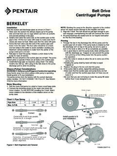
Transcription of S.A.E. Engine-Mount Centrifugal Pump - Berkeley …
1 OWNERS MANUALINSTALLATION, REPAIR, AND OPERATING Engine-Mount Centrifugal PumpIMPORTANTFor best possible performance and continuous, satisfactory operation,read these instructions before installing your new service be required, this manual can be a valuable guide. It should be kept near the installation for ready reference. Record nameplate data from pump on blank nameplate inside this manual for future pumps / 293 Wright Street / Delavan, WI 53115F00636(Rev. 7/21/09) INSTALLATIONG eneral Information ..3,4,5 Flywheel Coupling ..6,7 Pump to engine Rotation ..9 Suction Connection ..10,11 Discharge Connection ..12,13 START-UPPriming ..14,15 Operation ..15 MAINTENANCEG eneral Information.
2 16 Packing Ring Replacement ..17 Impeller Removal ..18 Seal/Impeller Replacement ..19 Shaft Maintenance/Replacement ..20 General Pump Inspection Check List ..22 PUMP NOMENCLATUREG eneral Information ..23 Parts Breakdown ..24,25 2F00636 Table of ContentsF00636 Page 3 Safety FirstGeneral InformationREAD AND FOLLOW SAFETY instructions !This is the safety alert you see thissymbol on your pump or in this manual, look for oneof the following signal words and be alert to thepotential for personal injury:DANGER warns about hazards that willcauseserious personal injury, death or major propertydamage if about hazards that will or cancause serious personal injury, death or majorproperty damage if about hazards that willor cancause minor personal injury or property damageif label NOTICE indicates special instructionswhich are important but not related to read and follow all safety instructions inthis manual and on safety labels in good condition.
3 Replace missing or damaged safety SafetyDo not allow pump, piping, or any other system com-ponent containing water to freeze. Freezing maydamage system, leading to injury or flooding. Allowingpump or system components to freeze will approved liquids only with this inspect pump and system safety glasses at all times when working work area clean, uncluttered and properly lighted;store properly all unused tools and visitors at a safe distance from the work parts. Can catchhands, feet, or clear of equipment andkeep shields in place whilepump is running. Stop motor or engine beforeservicing owner s manual beforeusing 4F00636 General InformationInstallationLOCATIONL ocate the pump as near the water source as practical.
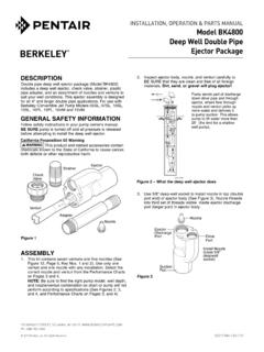
4 Makepipe run short, straight and with as few pipe fittings as pos-sible, to keep total friction loss to a pump in a clean, dry and drained location if possibleand protect against moisture and adverse weather should be located on a level, hard surface to preventshifting or tipping. Locate to be readily accessible for in-spection and of the portable nature of this style pump, carefulattention should be taken to assure that Net Positive SuctionHead Available (NPSHA) exceeds Net Positive Suction HeadRequired (NPSHR) by the pump or reduced performance andsevere pump damage may result. Figure 1, illustrates where these terms (NPSHA / NPSHR)come from, and how to determine if the pumping conditions atwhich you want to operate meet the proper criteria.
5 When indoubt, consult your nearest Berkeley Professional : If pump site is 1000 feet above sea level, subtract from the NPSHA equation and an additional feet foreach additional 1000 feet of FOUNDATIONCRUSHING with largersuction and discharge openings are extremely heavy. Use careand proper equipment when handling pump for sure to allow for the weight of the water in the pump installation :Pump should be placed on an area that will provide a solidfoundation substantial enough to support the weight of pumpand engine and also to provide stability while the pump isrunning. engine vibration will cause shifting on any type ofloose surface and cause piping strains and possible : Settling and/or shifting during operation can causepiping to place excessive strain on the pump and maydamage pump installation :Pump and engine should be set on a concrete foundationwhich is sufficiently substantial to absorb vibration and whichwill provide a permanent and rigid support.
6 Bolt engine directlyto piping should be at least one commercial pipe sizelarger than pump connections and flow velocity should notexceed eight (8) feet per of piping with pump case orexcessive pipe strain can cause distortion of pump com-ponents resulting in rubbing, breakage and reduced pump life. Insure that piping is supported in a manner that prevents theexertion of force on pump connections. If ANSI type flangeconnections are used, this can be checked by the followingprocedure. With the pump shut down, remove pipe flangebolts. If the mating flanges come apart or shift, misalignmentis present and causing pressure on the connections.
7 Adjustpipe supports until flanges mate without any force. Thisprocedure can be done throughout piping 200 300 400 500 600 700 800 9000010203050100150200 TDHNPSH in FeetGallons Per MinuteNPSHREXAMPLEONLYNPSHR at this point = 10 FeetNPSHR at this point = 14 FeetA Model B3 ZQM operating at 500 GPMwith 80 Feet of Head has a NPSHR 10 Feetat that point on the performance Model B3 ZQM operating at 600 GPMwith 68 Feet of Head has a NPSHR 14 Feetat that point on the performance RPMNPSHA7 FeetStatic LiftStatic Lift = FeetTheoretical staticlift of centrifugalpump at sea level =Total = FeetTotal Friction Loss = FeetSafety Factor - FeetMinus FeetPractical Limit =
8 FeetNPSHA = Feet total friction loss@ 500 Gallons per Feet total friction loss@ 600 Gallons per FeetOKNPSHA = FeetCAVITATION6044 0609500 GPM600 GPMF igure 1 EXAMPLEONLYSUCTION PIPINGR efer to illustrations on Page 10 and 11 for recommended andnot recommended practices in suction PIPINGR efer to illustrations on Page 12 and 13 for recommended andnot recommended practices in discharge FOR PROPER OPERATIONPump End:When delivering the required capacity (GPM) to the systempiping, the pump must add the amount of Head required bythe system at that capacity. The operating head-capacity pointshould be as close as possible to the highest efficiency lineshown on the performance curve, and MUST be below thehead-capacity line labeled Maximum RPM.
9 The maximumoperating RPM for the pump is determined by bearing life, orin some cases, by the pressure limits of the pump. Themaximum working pressure for NPT tapped and flangedpumps, per ANSI class 125, is 175 PSI unlessotherwise stated on the pump curve . When used as a boosterpump, the pressure at the pump discharge (combination ofinlet pressure plus pressure added by the pump) must notexceed the maximum working pressure shown. The SuctionNPSHA must be greater than the NPSHR shown on the :The engine used to drive the pump must be suitable for theapplication. It must produce adequate power for the pumpdemand, and must rotate in the correct direction (standardrotation is CLOCKWISE when viewed from the front ofengine).
10 Internal Combustion Engines are variable speed and variablepower machines. The power output depends upon the enginespeed (RPM) and will be reduced when operating altitude,and/or the air temperature increases. When driving the pumpat the RPM required to deliver water into the system piping,the engine must operate within the engine manufacturersminimum and maximum RPM limits. The power output tosupply the pump power demand must not exceed theCONTINUOUS POWER RATING of the engine , after deratingfor all power consuming engine accessories, and adjustmentfor installation site altitude and air temperature. Proper powermatching of the pump and engine is the responsibility of thepump and engine unit PUMP END TO Bracket Size:Type B engine drive pumps are available to fit engineshaving a standard 5 through 1 flywheel a new engine , the engine supplier can provide the an existing engine , the flywheel housing bore and boltcircle can be measured and compared against the housing dimensions listed in Table I, to identify thehousing number.