Transcription of SBOS477B –DECEMBER 2011–REVISED DECEMBER 2016 …
1 Product Sample & Technical Tools & Support & Reference Folder Buy Documents Software Community Design OPA1652, OPA1654. SBOS477B DECEMBER 2011 REVISED DECEMBER 2016. OPA165x SoundPlus Low Noise and Distortion, General-Purpose, FET-Input Audio Operational Amplifiers 1 Features 3 Description 1 Low Noise: The OPA1652 (dual) and OPA1654 (quad) FET-input nV/ Hz at 1 kHz operational amplifiers achieve a low Hz noise density with an ultra-low distortion of at 1. nV/ Hz at 10 kHz kHz. The OPA1652 and OPA1654 op amps offer rail- Low Distortion: at 1 kHz to-rail output swing to within 800 mV with a 2-k.
2 Low Quiescent Current: load, which increases headroom and maximizes 2 mA per Channel dynamic range. These devices also have a high Low Input Bias Current: 10 pA output drive capability of 30 mA. Slew Rate: 10 V/ s These devices operate over a very-wide-supply range of V to 18 V, or V to 36 V, on only 2 mA of Wide Gain Bandwidth: 18 MHz (G = 1). supply current per channel. The OPA1652 and Unity-Gain Stable OPA1654 op amps are unity-gain stable and provide Rail-to-Rail Output excellent dynamic behavior over a wide range of load Wide Supply Range: conditions.
3 V to 18 V, or V to 36 V These devices also feature completely independent Dual and Quad Versions Available circuitry for lowest crosstalk and freedom from interactions between channels, even when overdriven Small Package Sizes: or overloaded. Dual: SO-8 and MSOP-8. Quad: SO-14 and TSSOP-14 The OPA1652 and OPA1654 temperature ranges are specified from 40 C to +85 C. 2 Applications SoundPlus . Analog and Digital Mixers Device Information(1). Audio Effects Processors PART NUMBER PACKAGE BODY SIZE (NOM). Musical Instruments SOIC (8) mm mm A/V Receivers OPA1652 VSSOP (8) mm mm DVD and Blu-Ray Players WSON (8) mm mm Car Audio Systems SOIC (14) mm mm OPA1654.
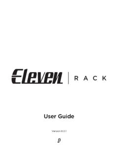
4 TSSOP (14) mm mm (1) For all available packages, see the orderable addendum at the end of the data sheet. Input Voltage Noise Spectral Density 1000. 9 ROWDJH 1 RLVH 6 SHFWUDO 'HQVLW\ Q9 +]. 100. 10. 1. 1 10 100 1k 10k 100k 1M 10M. Frequency (Hz) C006. 1. An IMPORTANT NOTICE at the end of this data sheet addresses availability, warranty, changes, use in safety-critical applications, intellectual property matters and other important disclaimers. PRODUCTION DATA. OPA1652, OPA1654. SBOS477B DECEMBER 2011 REVISED DECEMBER 2016 Table of Contents 1 Features.
5 1 8 Application and Implementation .. 18. 2 Applications .. 1 Application 18. 3 Description .. 1 Typical Application .. 21. 4 Revision 2 9 Power Supply 24. 5 Pin Configuration and Functions .. 3 10 24. 6 5 Layout Guidelines .. 24. Absolute Maximum Ratings .. 5 Layout Example .. 25. ESD 5 Power Dissipation .. 25. Recommended Operating 5 11 Device and Documentation Support .. 26. Thermal Information: OPA1652 .. 6 Device 26. Thermal Information: OPA1654 .. 6 Documentation Support .. 27. Electrical Characteristics: VS = 15 7 Related Links.
6 27. Typical Characteristics .. 8 Receiving Notification of Documentation Updates 27. 7 Detailed Description .. 14 Community 27. Overview .. 14 Trademarks .. 27. Functional Block Diagram .. 14 Electrostatic Discharge Caution .. 27. Feature 14 Glossary .. 28. Device Functional 17 12 Mechanical, Packaging, and Orderable Information .. 28. 4 Revision History NOTE: Page numbers for previous revisions may differ from page numbers in the current version. Changes from Revision A (August 2016) to Revision B Page Added new SON (8) package and body size information to Device Information table.
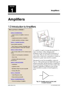
7 1. Added new pinout drawing for OPA1652 DRG (WSON) package .. 3. Added thermal information for the DRG (WSON) package in the Thermal Information 6. 2 Submit Documentation Feedback Copyright 2011 2016, Texas Instruments Incorporated Product Folder Links: OPA1652 OPA1654. OPA1652, OPA1654. SBOS477B DECEMBER 2011 REVISED DECEMBER 2016. 5 Pin Configuration and Functions OPA1652 D and DGK Packages 8-Pin SOIC and VSSOP OPA1652 DRG Package Top View 8-Pin WSON With Exposed Thermal Pad Top View OUT A 1 8 V+. OUT A 1 8 V+.
8 IN A 2 7 OUT B. IN A 2 7 OUT B. +IN A 3 6 IN B Thermal Pad +IN A 3 6 IN B. V 4 5 +IN B. V 4 5 +IN B. Not to scale Not to scale Pin Functions: OPA1652. PIN. I/O DESCRIPTION. NAME NO. IN A 2 I Inverting input, channel A. +IN A 3 I Noninverting input, channel A. IN B 6 I Inverting input, channel B. +IN B 5 I Noninverting input, channel B. OUT A 1 O Output, channel A. OUT B 7 O Output, channel B. V 4 Negative (lowest) power supply V+ 8 Positive (highest) power supply Exposed thermal die pad on underside of DRG package; connect thermal die pad to V.
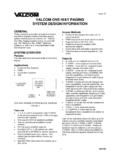
9 Thermal pad . Soldering the thermal pad improves heat dissipation and provides specified performance Copyright 2011 2016, Texas Instruments Incorporated Submit Documentation Feedback 3. Product Folder Links: OPA1652 OPA1654. OPA1652, OPA1654. SBOS477B DECEMBER 2011 REVISED DECEMBER 2016 OPA1654 D and PW Packages 14-Pin SOIC and TSSOP. Top View OUT A 1 14 OUT D. IN A 2 13 IN D. +IN A 3 12 +IN D. V+ 4 11 V . +IN B 5 10 +IN C. IN B 6 9 IN C. OUT B 7 8 OUT C. Not to scale Pin Functions: OPA1654. PIN. I/O DESCRIPTION.
10 NAME NO. IN A 2 I Inverting input, channel A. +IN A 3 I Noninverting input, channel A. IN B 6 I Inverting input, channel B. +IN B 5 I Noninverting input, channel B. IN C 9 I Inverting input, channel C. +IN D 10 I Noninverting input, channel C. IN D 13 I Inverting input, channel D. +IN D 12 I Noninverting input, channel D. OUT A 1 O Output, channel A. OUT B 7 O Output, channel B. OUT C 8 O Output, channel C. OUT D 14 O Output, channel D. V 11 Negative (lowest) power supply V+ 4 Positive (highest) power supply 4 Submit Documentation Feedback Copyright 2011 2016, Texas Instruments Incorporated Product Folder Links: OPA1652 OPA1654.