Transcription of SECTION 03470 TILT-UP PRECAST CONCRETE
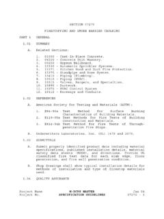
1 Project Name M-DCPS MASTER July 99 Project No. SPECIFICATION GUIDELINES 03470 - 1 SECTION 03470 TILT-UP PRECAST CONCRETE PART 1 GENERAL SUMMARY A. Work includes, but is not limited to, the following: 1. PRECAST wall panels. 2. Forms and casting beds. 3. CONCRETE . 4. Reinforcing steel and accessories. 5. Lifting inserts. 6. Brace inserts. 7. Erection and bracing. B. Comply with SECTION 03300 Cast-In-Place CONCRETE unless specified otherwise in this SECTION . C. Items installed under this SECTION but specified elsewhere, include, but are not limited to, embedded plates and anchors for connection to other materials.
2 SUBMITTALS A. CONCRETE Mix Designs: For each mix variation specified. B. Manufacturer's Literature: Manufacturer's specifications and application instructions for bond breaker. C. Shop Drawings shall include the following: 1. Reinforcing steel. 2. Layout drawings showing detail placement of embedded plates and anchors. 3. Layout drawings showing detail placement of lifting inserts and brace inserts. 4. Rigging arrangement, cable lengths, bracing arrangement, and panel weights. PART 2 PRODUCTS CONCRETE REQUIREMENTS A. Compressive Strength: 3,000 psi at 28 days. B. Slump: 4 inches + 1". Project Name M-DCPS MASTER July 99 Project No.
3 SPECIFICATION GUIDELINES 03470 - 2 C. Air Content: 5 percent + 1 percent. MATERIALS A. Bond Breaker: Compatible with coating, adhesive, or sealant applied to panel surface. B. Lifting and Bracing Inserts: Size and type required for each panel as shown on approved shop drawings. PART 3 EXECUTION PREPARATION A. Provide level, steel troweled casting surfaces. B. Sweep clean. C. Bond Breaker: 1. Apply minimum of 2 coats of bond breaker material according manufacturers published instructions, second coat at 90 degrees to first. 2. Inspect each panel to insure adequate coverage. 3. Do not apply bond breaker material after placement of reinforcing bars. EMBEDDED ITEMS A.
4 Place embedded plates, anchors, and inserts accurately according to approved layout shop drawings. B. Tie securely to prevent dislocation during placing of CONCRETE . C. Do not weld embedded items to reinforcing unless additional reinforcing is provided specifically for this purpose. D. Do not weld lifting inserts. E. Notify A/E if embedded items are cast into panel in wrong locations. F. Do not field modify connections without specific instructions or approval by A/E. FINISHES A. Trowel Finish: Finish top face as specified in SECTION Project Name M-DCPS MASTER July 99 Project No. SPECIFICATION GUIDELINES 03470 - 3 03300 Cast-In-Place CONCRETE .
5 B. Tolerances: Fabrication tolerances are as follows: 1. Length and Height: a. Up to 10 feet: + 1/8", - 3/8". b. 10 feet to 20 feet: + 1/8", - 1/2". c. Over 20 feet: + 1/8", - 3/8". 2. Thickness: Overall + 3/16". 3. Straightness (deviation from intended line): a. Up to 10 feet: " 3/8". b. 10 feet to 20 feet: " 5/8". c. 20 feet to 40 feet: + 3/4". 4. Skewness (measured as tolerance in length of diagonal): a. Up to 10 feet: + 3/8". b. 10 feet to 20 feet: + 5/8". c. 20 feet to 40 feet: + 3/4". ERECTION A. Do not erect panels until CONCRETE is 14 days old unless CONCRETE strength has been verified by cylinder testing to be 3,000 psi minimum. B. Use spreader beams and cable rigging as shown on approved shop drawings.
6 C. Minimum cable lengths as indicated. D. Inspect inserts at start of lift to insure connections are holding properly. E. Lift in a continuous process until panel is vertical. F. Avoid intermediate stops. G. Lower panels into position on shims or grout pads. H. Install bracing securely before removal of rigging. STRUCTURAL GROUTING A. Install grout under CONCRETE panels. B. Dry Pack Sand Cement: Project Name M-DCPS MASTER July 99 Project No. SPECIFICATION GUIDELINES 03470 - 4 1. Mix: One part Portland cement, 2-1/2 parts sand that will pass screen, and sufficient water to produce grout that will stick together, but not exude water and not be rubbery or crumbly.
7 2. Begin dry pack placement and compaction against solid backing. 3. In lieu of dry pack material, flowable factory mixed nonshrink grout may be used. 4. Do not use truck mixed grout. C. Placement: 1. Place grout as soon as possible after CONCRETE panels have been plumbed and secured in position. 2. Clean space of water and debris before placing grout. 3. Pack fully under panels. SURFACE TREATMENT A. Exterior face of panels shall receive smooth form finish. Interior face of panels shall receive trowel finish as specified in SECTION 03300, Cast-In-Place CONCRETE . B. Rubbed finish of interior or exterior faces of panels is not required. C. Patch and rub holes made by lifting inserts.
8 END OF SECTION
