Transcription of Sensor Connections - Banner Engineering
1 Sensor Connections Sensor Connections The Sensor Connections guide lists most common Banner and non- Banner sensors and how to wire them to the DX80. devices. This reference guide lists typical Connections . If you have additional questions about a specific Sensor or its connection instructions, please contact Banner Engineering or the manufacturer of the Sensor you are using. Discrete Sensors. Neither the inputs nor the outputs on the DX80 devices are isolated. Under certain operating conditions, externally powered sensors may need to have ground in common with the DX80 device to which they are connected. The power sources do not have to be the same. analog Sensors. For analog sensors, the ground/dc common of the Sensor should be connected to the ground of the DX80 device. For best results, Banner recommends that the power source for the Sensor and DX80 device is the same.
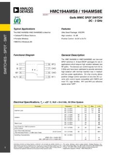
2 Discrete Inputs Discrete Sensors. Neither the inputs nor the outputs on the DX80 devices are isolated. Under certain operating conditions, externally powered sensors may need to have ground in common with the DX80 device to which they are connected. The power sources do not have to be the same. Discrete Inputs, Sourcing Two-Wire Sensors Three-Wire Sensors 10-30V dc PWR. PWR. 10 30V dc Discrete IN. Discrete IN. GND. dc common Wiring diagram for a sourcing (PNP), two-wire Sensor Wiring diagram for a sourcing (PNP), three-wire Sensor powered using the SureCross device terminal block. powered using the SureCross device terminal block. Under certain conditions, the dc commons between the Sensor and The Sensor 's power source might need to be the same as the SureCross device might need to be connected. the SureCross device power source. The Sensor 's power source might need to be the same as the SureCross device power source.
3 Discrete Inputs, Sinking Two-Wire Sensors Three-Wire Sensors Discrete IN PWR. 10-30V dc Discrete IN. GND. dc common GND. dc common Wiring diagram for a sinking (NPN) two-wire Sensor Wiring diagram for a sinking (NPN) three-wire Sensor powered using the SureCross device terminal block. Under powered using the SureCross device terminal block. Under certain conditions, the dc commons between the Sensor and certain conditions, the dc commons between the Sensor and the SureCross device might need to be connected. the SureCross device might need to be connected. Datasheet 29 January 2014. Sensor Connections Discrete Inputs, MINI-BEAM. MINI-BEAM. MINI-BEAM Discrete IN. SP1. Two-wire MINI-BEAM Sensor using a FlexPower Node and powered using the Node's switch power. Discrete Outputs Discrete Outputs Sourcing (PNP) Sinking (NPN). PWR. PWR. 10-30V dc 10-30V dc Discrete OUT.
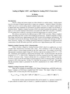
4 Load Discrete OUT. Load GND. GND dc common dc common Wiring diagram for a sourcing (PNP) two-wire output load Wiring diagram for a sinking (NPN) two-wire output. Under powered using the SureCross device terminal block. Under certain conditions, the dc commons between the load and certain conditions, the dc commons between the load and the SureCross device might need to be connected. the SureCross device might need to be connected. The Sensor 's power source might need to be the same as the SureCross device power source. analog Inputs analog Sensors. For analog sensors, the ground/dc common of the Sensor should be connected to the ground of the DX80 device. For best results, Banner recommends that the power source for the Sensor and DX80 device is the same. analog Inputs, Powered using SureCross Device Terminals Two-Wire Sensors Three-Wire Sensors PWR PWR.
5 10-30V dc 10-30V dc Sensor analog IN analog IN. + + . Sensor GND GND. dc common dc common Two-wire analog Sensor powered from a 10 30V dc power Three-wire analog Sensor powered from 10 30V dc power SureCross device using the PWR terminal. SureCross device using the PWR terminal. Do not exceed analog input ratings for analog inputs. Only Do not exceed analog input ratings for analog inputs. Only connect Sensor outputs to analog inputs. connect Sensor outputs to analog inputs. 2 - tel: 763-544-3164 Datasheet Sensor Connections analog Inputs, Powered from switch Power Two-Wire Sensors Three-Wire Sensors SPx SPx + Sensor +. analog IN analog IN . + + . Sensor GND GND. dc common dc common Two-wire analog Sensor or two-wire NAMUR proximity Three-wire analog Sensor using a FlexPower Node and Sensor using a FlexPower Node and powered using the powered using the Node's switch power.
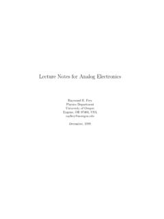
6 Node's switch power. Do not exceed analog input ratings for analog inputs. Only Do not exceed analog input ratings for analog inputs. Only connect Sensor outputs to analog inputs. connect Sensor outputs to analog inputs. analog Inputs, Powered Externally Do not exceed analog input ratings for analog inputs. Only connect Sensor outputs to analog inputs. Two-Wire Sensors Three-Wire Sensors analog IN analog IN. external power + external power + . Sensor Sensor GND GND. dc common dc common Two-wire analog Sensor using a FlexPower Node but the Three-wire analog Sensor using a FlexPower Node but the Sensor is powered externally (not from the SureCross Sensor is powered externally (not from the SureCross device). device). analog Inputs, Temperature Sensors Thermocouple RTD. A1+. Ax+. +. TC. Ax . A1 . DI1. TC Type - Wire + Wire This wiring diagram applies to a standard three-wire RTD.
7 Sensor . When using thermocouple and RTD sensors, the J red white quality of the power supply influences the accuracy of the K red yellow signal. R red black Datasheet - tel: 763-544-3164 3. Sensor Connections analog Inputs, QT50U Long-Range Ultrasonic Sensor QT50U Ultrasonic Sensor Four-wire QT50U Sensor , using a FlexPower Node, and A1+. powered using the Node's switch power terminal. The (wh). QT50U QT50U output is set to 4 20 mA. A1 Do not apply power to the Ax+ connection. (bk). GND. dc common (bu). SP1. Sensor power (bn). analog Outputs analog Outputs, Three-Wire Sensors Powered from the SureCross Terminals Powered Externally PWR external power 10-30V dc AOx AOx Sensor Sensor GND GND. dc common dc common Three-wire analog output device powered by the SureCross Three-wire analog output device powered externally (not device. from the SureCross device).
8 analog Outputs, Drive Motor Controllers AI- Referenced to Ground AI- Not Referenced to Ground AOx AI+ AOx AI+. Drive/motor drive/motor controllers controller GND AI . GND. AI . When the AI- can be referenced to ground, use this wiring When the AI- cannot be referenced to ground, use this diagram for drive/motor controllers. wiring diagram for drive/motor controllers. - tel: 763-544-3164.