Transcription of Series 39 Pneumatic Actuator - Cryogenics Experts, …
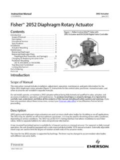
1 Worcester Controls PB 302-34. AN ISO 9001 REGISTERED COMPANY. Series 39 Pneumatic Actuator Twin piston double rack-and-pinion Pneumatic Actuator offers long cycle life for rotary applications Flow Control Division Worcester Controls Series 39 Pneumatic Actuators High cycle Pneumatic power for on-off or throttling control of rotary valves and dampers Namur (VDI/VDE) top mounting Position indicator for easy fitting and provides external indication interchangeability of switches, of valve position One-piece steel pinion drive positioners, etc. with full length, nickel coated rack/pinion tooth engagement for Coro-lube coated aluminum greater operational life construction for corrosion resistance and superior wear Stainless steel fasteners performance on internal and improve aesthetics and ease external surfaces of maintenance Corrosion protected springs for long service life Unique unrestricted air flow through guide rods *Polished gives fast operation stainless steel speeds as standard piston guide rods minimize internal wear and maximize performance life Long screws to allow complete release of spring energy for safe Balanced double disassembly when required rack-and-pinion ISO 5211 mounting pattern Multi-spring concept eliminates side loads for interchangeability of mounting provides variable torque/air kits and greater mechanical strength pressure performance from the same
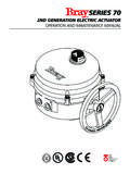
2 Actuator * Size 0539 does not utilize piston guide rods. Features and Benefits Available as spring return All parts sealed and greased for Can be mounted for fail-open or double acting life, no maintenance required or fail-closed operation Large range of sizes for Safe disassembly, no Backed by our exclusive efficient torque matching special tools required two-year warranty 2. Flow Control Division Worcester Controls Operating Principle DOUBLE ACTING Actuator 39. TOP VIEW. PORT 1. AIR SUPPLY. PORT 2. VENT OUT. STROKE OPENING. TOP VIEW. PORT 1. AIR EXHAUST. The Series 39 Pneumatic Actuator design is based on the opposed rack-and-pinion principle utilizing piston guide rods to guarantee part alignment. The PORT 2. fully supported guide rods minimize friction and VENT IN. wear between the pistons and the body bore. In the double acting Actuator , compressed air is applied to Port 1.
3 The air flows through the rear STROKE CLOSING. guide rod, enters the center chamber to push the pistons apart, turning the shaft counter-clockwise (as seen from above) to open the valve. During this SPRING RETURN Actuator 39S. TOP VIEW. action, air in the end caps is vented through Port 2. PORT 1. via the front guide rod. Action is reversed, the AIR SUPPLY. valve is closed, by applying air to Port 2 and venting air through Port 1. In a fail-safe spring return Actuator , springs are nested in the end caps. The number of springs in each cap depends on the available supply air PORT 2. VENT OUT. pressure and required torque output. Air is supplied through Port 1 to the center chamber to push the pistons apart which compresses the springs. During this action, air in the end caps is vented through Port STROKE OPENING. 2 via the front guide rod.
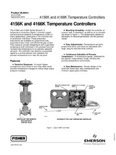
4 When air is vented out TOP VIEW. through Port 1 (via a three-way solenoid valve) the PORT 1. springs push the pistons back together thus closing AIR EXHAUST. the valve. Port 2 is continuously vented. The springs provide a dependable, safe closure in the event of electrical or air supply failure. PORT 2. VENT IN. STROKE CLOSING 3. Flow Control Division Worcester Controls Product Specifications Pneumatic Actuators shall be of a dual- The rack shall be machined as part of the Actuators shall have optional integral end- piston design for compactness, highest piston in order to extend the Actuator life mounted limit switches, reducing overall torque output, minimal air consumption and and eliminate hysteresis. height and allowing the use of extended even weight distribution (balanced) on the Actuator shafts as manual override. Actuator housings shall be protected both valve stem.
5 Internally and externally with a nickel acetate Actuators shall have optional integral Actuators shall be equipped with two piston filled coating for corrosion resistance. solenoid valving without the use of transfer guide rods to bear the lateral rack-and- tubes. Valving shall incorporate fail-safe Single acting actuators shall use multi- pinion thrust forces, increasing piston seal action upon interruption of electrical signal. springs at each end to eliminate uneven life and eliminating the possibility of cylinder forces on the pistons and shall be field Actuator manufacturer shall offer the scratching by the pistons. Elastomeric seals adaptable to reduced pressure air supplies. minimum of a two-year warranty. shall not be loaded as bearings. Actuators shall have external extended As manufactured and offered by Flowserve. The torque shall be generated through a shafts for position indication and manual double rack-and-pinion gearing mechanism override capability.
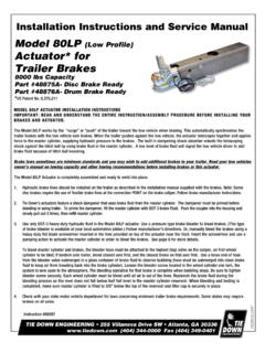
6 With full-length, uninterrupted engagement of the rack-and-pinion teeth. Parts List/Material Specifications 2 10. 1 3. 6 4. 7 5. 9. 8. ITEM NO. DESCRIPTION MATERIAL/FINISH. 1 Body Aluminum (Extrusion) Anodized 2 Pinion Carbon Steel (Corrosion Resistant Coated). 3 Pistons Aluminum 4 End Caps Aluminum Anodized 5 Guide Rods Stainless Steel 6 Bearings Acetal 7 O Rings Nitrile Rubber 8 End Cap Screws Stainless Steel 9 Springs Chrome Silicon (Corrosion Resistant Coated). 10 Position Indicator Polyethylene 4. Flow Control Division Worcester Controls Solenoid Mounting SOLENOID BLOCK - DIRECT MOUNTED General Purpose TYPE1. Solenoid Coil Data Solenoids are available The solenoid end cap of each Actuator is pre-drilled to allow rapid (Class A Coil) in the following types: attachment of either a double acting or spring return solenoid VOLTAGE INRUSH AMPS HOLDING AMPS General Purpose TYPE 1.
7 Control block. 24 VAC 50/60 HZ .80. Watertight TYPE 4, 4x;. 120 VAC 50/60 HZ .30 .15. 240 VAC 50/60 HZ .12 .08 Hazardous Locations The double acting solenoid control block provides extremely fine and 12 VDC .70. 24 VDC .35 TYPE 7 (UL & CSA listed independent adjustments for speed control on the opening and closing for Class I, Division I, strokes of a double acting Actuator (20:1 ratio). The double acting Watertight/Hazardous Locations TYPE Groups A, B, C & D) and solenoid control block can be overridden by manual operation of the 4, 4x, 7 & 9 Solenoid Coil Data TYPE 9 (UL & CSA listed control block spool. (Class F Coil). for Class II, Groups E, F. VOLTAGE INRUSH AMPS HOLDING AMPS. The spring return solenoid control block provides an optional adjustment 24 VAC 50/60 Hz .71. & G). The Type 7. for speed control on the spring stroke of a spring return Actuator .
8 120 VAC 50/60 Hz .23 .14 solenoid is also rated 240 VAC 50/60 Hz .11 .07. 12 VDC .81 Type 4, 4x. Both double acting and spring return styles will return to the 24 VDC .41. Actuator closed position (pistons together) upon electrical failure. Four-Way Double Acting Solenoid Three-Way Spring Return Solenoid Speed Speed Control Control Nut Screws (Standard). (Standard). Manual Override Namur Solenoid Interface Optional Namur VDI/VDE 3845 interface end caps and direct mount Namur solenoids are available making the Series 39 a truly international Actuator . All ports are G 1/4 except size 05 and 10, which are G 1/8. Consult table on back cover for ordering details. Three-way Namur solenoids include a standard rebreather feature. Namur End Cap Namur (designated V64) Mounted Solenoid 5. Flow Control Division Worcester Controls Spring Return Actuator Torque Output 30 ( ) 40 ( ) 50 ( ).
9 Operating Pressure 60 ( ) 70 ( ) 80 ( ) psi (Bar). No. of Springs 2 4 6 8 8 10. Sizing Model Stroke Start End Start End Start End Start End Start End Start End No. Determine appropriate valve torque Air 70 40 85 60 105 60 125 70 170 120 175 95 in-lb Nm requirements from valve literature. For double 1039 Spring 58 35 60 35 95 55 125 75 125 75 160 95 in-lb Nm acting actuators, select the Actuator whose Air 140 60 130 85 200 125 240 150 260 155 325 190 in-lb Nm torque output at available air supply exceeds 1539. Spring 100 60 105 74 165 105 220 145 220 145 280 185 in-lb breakaway torque requirements of the valve. Nm Air 220 150 300 240 340 235 415 280 575 440 600 360 in-lb For detailed instructions, consult Worcester 2039. 65 Nm Spring 140 95 190 125 300 195 400 265 400 265 505 335 in-lb Controls' Ball Valve Actuator Selection Nm Manual, brochure V400.
10 Air 220 110 560 400 600 350 730 420 925 655 980 550 in-lb 2539 105 74 111 Nm Spring 240 170 345 210 540 330 720 450 720 450 915 575 in-lb 103 Nm For fail-closed, spring return actuators, select Air 324 180 840 610 965 600 1130 690 1575 1145 1650 920 in-lb the appropriate size Actuator whose torque 3039 108 128 178 129 186 104 Nm Spring 456 264 560 340 870 535 1160 730 1160 730 1470 920 in-lb output at end of the spring stroke (at available 131 131 166 104 Nm Air 1550 1160 1810 1200 2060 1220 2700 1860 2950 1900 in-lb air supply) is sufficient to close the valve. 175 131 205 136 233 138 305 210 333 215 Nm 3339. Spring 1070 680 1680 1070 2300 1460 2300 1460 2900 1850 in-lb 121 77 190 121 260 165 260 165 328 209 Nm For fail-open spring return actuators, select Air 1560 1260 2100 1470 2360 1450 2850 1730 3570 2615 3850 2210 in-lb appropriate Actuator whose torque output at 3539.